

by NOVA

Oct 31, 2026
Solar charge controller sizing requires separate checks for battery voltage, charging current, PV voltage, PV input current, and permitted array power. For an MPPT controller, array watts divided by battery voltage gives an initial output-current estimate, but that number alone cannot approve a model. You must also verify cold-weather open-circuit voltage, the operating-voltage range in hot conditions, battery charging limits, and any temperature derating. This guide provides a worked example and a worksheet for reviewing a standalone battery-based controller. It does not size an inverter or replace a qualified designer’s installation calculations.
If you have not chosen the charging technology, start with the MPPT vs PWM comparison. The formulas below distinguish MPPT battery-output current from array-input current rather than applying one current number everywhere.
Begin with the module datasheet, not only the total array wattage. Record rated power, maximum-power voltage and current, open-circuit voltage, short-circuit current, temperature coefficients, and the intended series/parallel arrangement. Values copied from different module models cannot form a valid calculation set.
For the battery, identify chemistry, nominal voltage, permitted charging-voltage range, maximum charging current, and temperature restrictions. Include requirements imposed by its battery-management system. Record whether another charger can operate at the same time and whether communications are required to authorize charging.
For each candidate controller, distinguish absolute maximum PV voltage from the MPPT operating range and startup requirements. Record maximum PV short-circuit current, any operating input-current limit, battery-side charge-current rating, permitted array power at the selected battery voltage, temperature derating, and battery-profile settings. These limits serve different purposes.
For a screening calculation, use:
Icharge ≈ PPV × η ÷ Vbattery
Here, charging current is in amperes, PV power is in watts, battery voltage is in volts, and conversion efficiency η is a decimal. This is a power-balance estimate, not a statement of the controller’s current rating. Real output is affected by available array power, charging control, and equipment limits.
The need to distinguish source power from converter output follows the operating-point and conversion principle described in TU Delft’s introduction to MPPT. Apply the manufacturer’s sizing instructions to the final model rather than treating an approximate formula as its approval rule.
Assume 600 W is available at the controller input and assume 95% conversion efficiency solely for this example. At a battery charging voltage of 28.8 V:
Icharge ≈ 600 × 0.95 ÷ 28.8 = 19.8 A.
If the same power were available while the battery was at 22 V, the estimate would become 25.9 A. The lower voltage is a hypothetical allowed operating point, not a recommended battery discharge setting. Use the actual battery and controller operating limits for a real system.
Thus, calculating only at a high charging voltage can understate the current that a conversion stage may need to deliver elsewhere in its operating range. For an initial lossless screening bound at 22 V, 600 ÷ 22 is approximately 27.3 A. A 30 A class may deserve further review, but it is not automatically approved: input limits, permitted PV power, thermal conditions, battery acceptance, and manufacturer-required allowances still matter.
The array may operate at a higher voltage and lower current while the battery receives a lower voltage and higher current. Reading 12 A at the PV input does not establish that a 12 A charging-output controller is sufficient. Similarly, a 40 A charge-current label does not mean the PV input permits 40 A of short-circuit current.
Conventional PWM controller selection follows its own array-current and voltage-matching requirements. Do not use MPPT power-conversion arithmetic as a substitute for a PWM manufacturer’s instructions. Any required design factors also need the applicable equipment instructions and local rules; there is no single multiplier that resolves every input, output, cable, and protection check.
Series-connected module voltages add. When a module has a negative voltage-temperature coefficient, colder cells increase its open-circuit voltage. PVEducation explains the temperature dependence of PV voltage. Use the exact module’s documented coefficient and the project’s prescribed design conditions.
Where the manufacturer permits a linear coefficient calculation, a simplified form is:
Voc,cold ≈ Nseries × Voc,reference × [1 + βVoc × (Tdesign − Treference)]
Convert a coefficient expressed in percent per degree to a decimal per degree before using it. Check whether a datasheet instead expresses its coefficient in volts per degree; that requires a different expression. The designer must select the appropriate temperature assumption rather than confusing ambient temperature with measured operating cell temperature.
For a separate stringing illustration, assume four identical 150 W modules, each with 22.5 V open-circuit voltage at 25°C, a coefficient of −0.28%/°C, and a design temperature of −10°C. These are invented example inputs, not MOES module specifications.
The correction factor is 1 + (−0.0028 × −35) = 1.098. Four modules in series therefore reach approximately 4 × 22.5 × 1.098 = 98.8 V. A candidate with a 90 V absolute maximum PV input fails this check even though the array is only 600 W.
Changing to two modules in series and two parallel strings reduces the calculated cold string voltage to 49.4 V. That resolves only the illustrated maximum-voltage issue. It does not prove the new arrangement is suitable: input current increases, hot-condition working voltage still needs checking, and all other controller limits remain relevant.
Array voltage falls as crystalline-silicon cell temperature rises. A string that is comfortably below the absolute maximum when cold may provide inadequate operating voltage when hot. Compare its expected working voltage with the candidate’s MPPT range, battery charging voltage, startup threshold, and any required voltage difference between PV and battery.
Do not assume all MPPT controllers can raise a low PV voltage to charge a higher-voltage battery. Confirm the converter’s supported operating relationship. Also distinguish startup from continued operation; a product may have separate requirements for each. Ask the supplier to confirm the proposed string arrangement at the relevant hot and cold design points.
For identical strings, series connection leaves string current approximately equal to module current, while parallel strings add their currents. If each example module has a hypothetical 8.7 A short-circuit current, the two-parallel-string arrangement has 17.4 A nameplate array short-circuit current before applying the required design allowances.
Check that value against the controller’s specified PV short-circuit-current limit using the manufacturer’s method and applicable project rules. Also check any separate operating-current limit. Neither is automatically the same as battery charging current, and neither replaces conductor and overcurrent-protection calculations.
Read permitted PV power at the actual battery voltage. Some controllers allow different array power on different battery banks, and some explicitly allow limited PV oversizing. Output clipping is permissible only within the approved arrangement. It does not make excessive PV voltage or input short-circuit current acceptable.
The worksheet combines the hypothetical 600 W screening case with the separate four-module stringing inputs above. Its numbers demonstrate the checks; they are not a product recommendation or a construction design.
| Check | Example result | Still required before approval |
|---|---|---|
| Nominal battery system | 24 V example bank | Supported voltage range, chemistry, and charging profile |
| Output-current estimate | 19.8 A at 28.8 V; 25.9 A at 22 V, assuming 95% efficiency | Full operating range, current limits, allowances, and thermal rating |
| Four-module series string | 98.8 V cold Voc | Fails the hypothetical 90 V maximum-input candidate |
| Two-series, two-parallel array | 49.4 V cold Voc | Hot Vmp, startup headroom, and remaining voltage conditions |
| Parallel-string Isc | 17.4 A nameplate value | Required allowances and exact PV input-current limit |
| PV array power | 600 W nameplate | Permitted array power at 24 V and oversizing policy |
| Installation environment | Not specified by the arithmetic | Ambient range, cooling clearance, enclosure conditions, and derating |
Confirm the battery can accept the proposed charge current, including current from other simultaneous chargers. A larger controller does not force its maximum current into every battery, but its settings and control behavior must implement the required limit. Review the specified response to communication loss, a battery-management-system stop request, and temperature restrictions.
Provide the mounting space and cooling conditions required by the manual. Do not infer an enclosure’s weather rating from its appearance, and do not place an indoor product outdoors because the PV modules are outdoors. Long cable runs, grounding arrangements, protection devices, isolation, and battery fault current require their own competent design review.
IEA PVPS Recommended Practices for Charge Controllers discusses adequate controller sizing and the need to consult manufacturers about rating allowances. It is a historical technical reference, not the current electrical code for every country. Use the current product instructions and the rules applicable to the project.
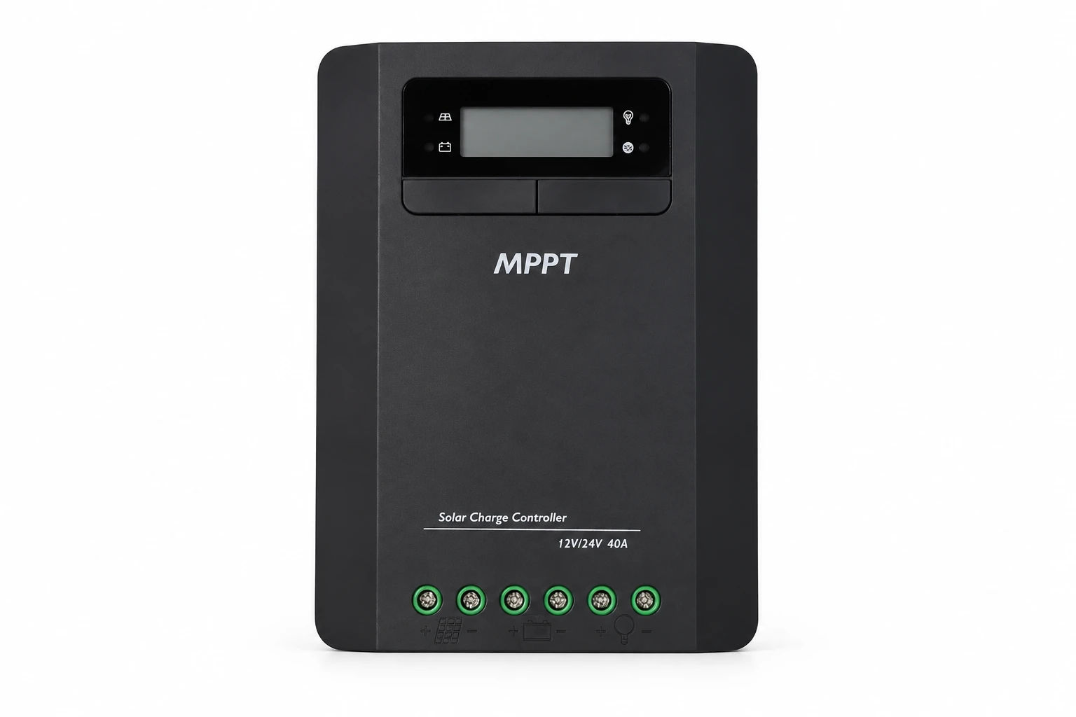
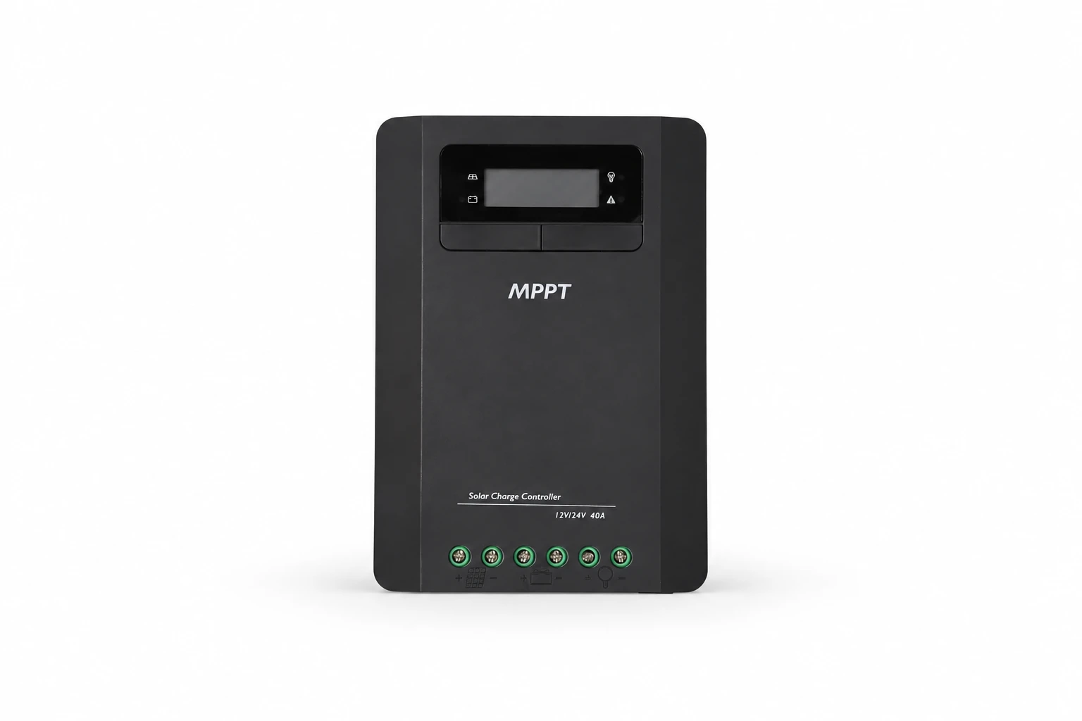
MOES lists multiple MPPT controller options, including the 40 A, 12/24 V controller listing. This identifies a candidate family; it does not establish that the example array is approved. Request the exact offered model, current manual, PV input limits, battery-voltage-specific power allowance, and derating information.
Send the completed worksheet with module and battery datasheets, the array diagram, site conditions, other charging sources, and the installation plan. For adjacent equipment, use the inverter datasheet review guide. Before assembling the PV leads, apply the connector compatibility checklist. Those reviews complement controller sizing rather than replace it.
TU Delft’s introductory MPPT lesson provides the background for separating PV-input and battery-output conditions. Follow the calculation and the exact manufacturer’s limits for actual selection.
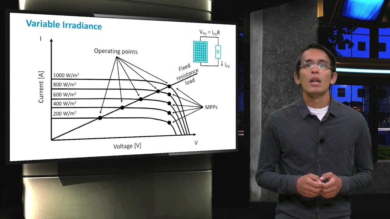
Watch TU Delft’s Introduction to MPPT.
That gives an initial battery-output-current estimate. Final selection also needs PV voltage, PV input current, permitted array power, battery compatibility, temperature conditions, and the manufacturer’s sizing method.
Do not assume so. An MPPT controller converts between operating voltages, and its PV-input limits can differ from its battery-output charge-current rating.
No. The controller’s maximum PV voltage is a separate limit. Exceeding it is not made acceptable by selecting a higher charging-current rating.
Only where the exact manufacturer explicitly allows the proposed oversizing and every voltage, current, power, and operating-condition limit remains satisfied.
No. Also check hot-condition working voltage, startup requirements, PV input current, charging current, battery settings, and installation conditions.


OTHER SMART DEVICES
Jun 13,2026
OTHER SMART DEVICES
Jun 12,2026
TUYA SMART HOME PRODUCTS
Jun 12,2026
 +86 137 3639 3028