

by NOVA

Oct 30, 2026
Solar connector compatibility depends on the exact mating pair, cable specification, electrical ratings, and assembly instructions—not simply whether two plugs click together. For a new PV installation, specify matched connector halves from the same manufacturer and approved product family. Treat a different-brand pairing as unresolved unless documentation explicitly covers that exact combination and the project’s applicable requirements. For distributors and EPC teams, the useful question is therefore: “What evidence identifies this connection as an approved assembly?” This guide explains how to answer it before ordering extension leads, replacement parts, or inverter connections.
Scope: This article concerns DC photovoltaic cable connectors. It does not provide a live-work procedure or approve a particular connector combination. MC4 is a Stäubli product name; “MC4-compatible” is often used loosely in catalogs and does not, by itself, establish approval to mate products.
A connector has several jobs at once: carry current through its metal contacts, retain those contacts in the housings, lock the housings together, and protect the connection from the environment. Two products can appear to fit while differing at one of these less visible interfaces. A successful hand assembly is consequently a useful observation, but an inadequate purchasing specification.
Imagine an extension lead whose housing resembles the plug fitted to a module. A buyer sees matching black plastic and a familiar latch. What remains unknown is whether the internal contact dimensions, engagement, seal arrangement, and approved assembly conditions correspond. Substituting a visually similar part transfers those unanswered questions into the finished array.
The U.S. Department of Energy’s PV system owner’s guide describes connector problems associated with poor crimps, incomplete contact installation, water ingress, and cross-mating. Its practical implication for procurement is straightforward: inspect the connection as a complete assembly rather than approving individual pieces from appearance alone.
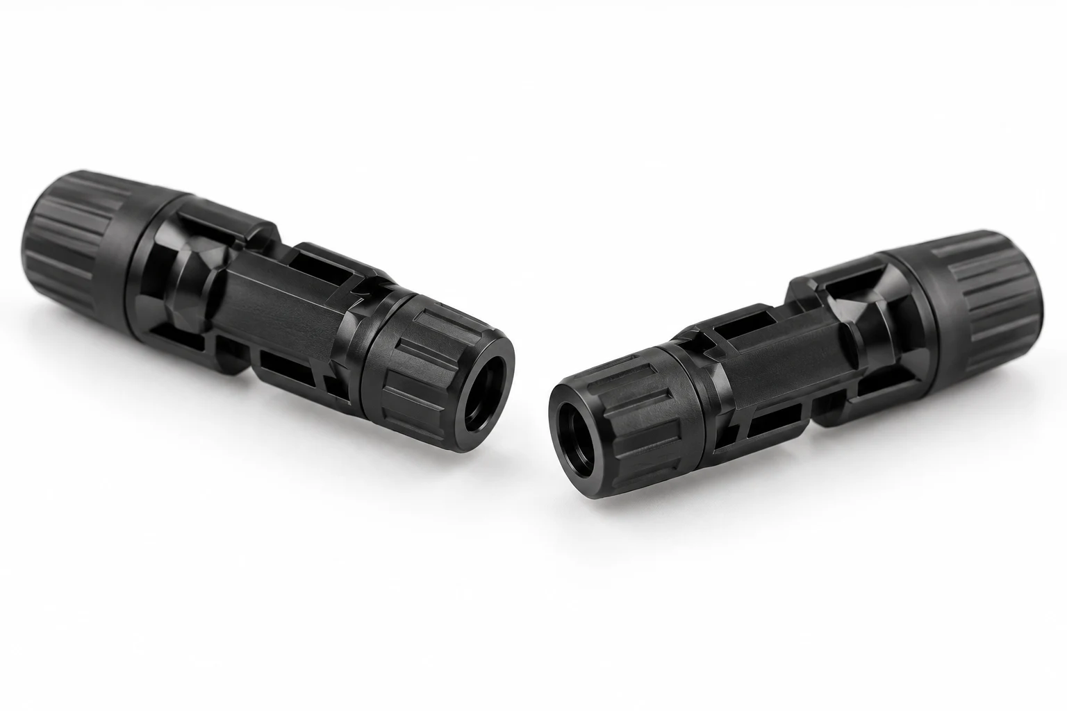
A conversation about a male connector may refer to its metal contact or to the outer housing shape. Those descriptions can cause purchasing mistakes when different people use different conventions. Positive and negative are circuit functions; they should not be inferred from an informal housing nickname.
Use a manufacturer’s part number, its drawing, and a contact description on the order. For cable assemblies, add an end-to-end polarity drawing and legible identification. The Sandia/NREL paper on standardized photovoltaic connector nomenclature addresses precisely this terminology problem. Consistent language helps a warehouse, harness supplier, and installer talk about the same physical components.
Use the following review table before releasing a connector or cable assembly. It is a practical evidence checklist, not a substitute for product certification, engineering approval, or the applicable local electrical rules.
| Review item | Evidence to request | Reason to stop the order |
|---|---|---|
| Mating identity | Manufacturer, family, and exact part numbers for both halves | Supplier identifies only an “MC4-style” shape |
| Pairing approval | Current instructions and certification information covering the proposed pair | Separate certificates are offered as proof of mixed-pair approval |
| Conductor fit | Cable construction and conductor size within the contact’s specified range | Wire size is selected only because it enters the housing |
| Sealing fit | Cable outer diameter and the matching gland or seal variant | Only the copper cross-section is documented |
| Electrical duty | Project voltage/current assessment and applicable temperature conditions | A family’s highest advertised rating is applied to every variant |
| Assembly method | Approved contact, tool, die, preparation, and tightening instructions | A generic crimper is assumed to suit all contacts |
| Traceability | Batch identity, supplier records, and controlled substitution process | Equivalent-looking parts can change without review |
Keep this record with the project bill of materials. A decision made during sample approval is useful only if the delivered components remain the same.
The metal contact must be suitable for the specified conductor, including its size and construction. Meanwhile, the cable gland seals around the outside of the insulation or jacket. A cable can satisfy the first condition and fail the second. The same nominal copper size does not guarantee the same outside diameter across cable constructions.
For example, a purchase request stating “6 mm² PV cable” remains incomplete if the selected connector’s sealing range is unknown. Ask for the cable manufacturer and part number, conductor construction, actual outside-diameter range, and the contact and seal variants proposed. Have the assembly supplier confirm the combination against current instructions before making production leads.
Do not solve an unsuitable gland fit with tape, improvised packing, extra sealant, or excessive tightening. Those changes create a different assembly from the one being evaluated. Obtain the correct documented components instead.
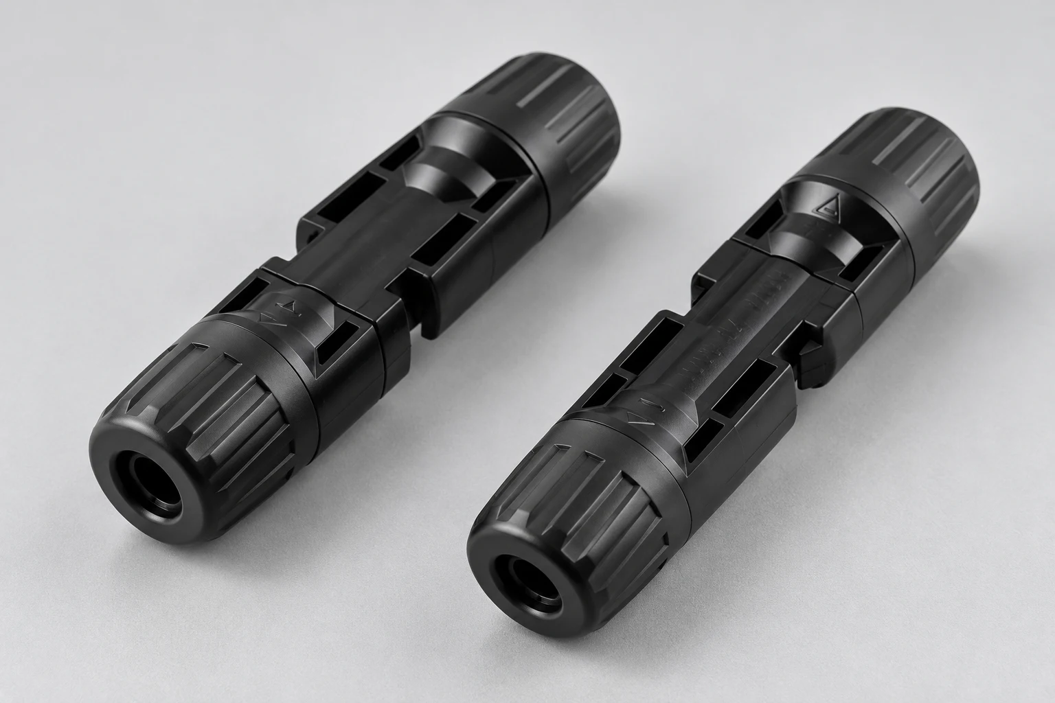
A rating on a catalog page needs its conditions. Confirm which exact variant carries that rating, which cable configuration it assumes, and which installation conditions apply. The project designer should assess the intended DC circuit, including the voltage and current conditions required by the applicable design rules. An inverter’s AC output rating does not define the duty of its PV connectors.
Likewise, an ingress-protection description applies to a specified assembly and test condition. It does not justify leaving unmated ends exposed, placing connectors in standing water, or ignoring the installation instructions. Ask how unused ends must be protected during storage and installation, and whether the stated protection depends on complete mating and correct cable entry.
For the surrounding system requirements, the solar inverter datasheet review guide helps separate connector questions from inverter input limits. Keep both reviews in the project file; approving one does not complete the other.
A certification reference is meaningful when it can be traced to the manufacturer, product identity, and scope being supplied. Request the relevant certificate or listing details and compare them with the actual parts. A logo in a brochure, an unrelated family certificate, or a statement that both brands follow the same standard leaves the exact proposed pairing unanswered.
When different manufacturers or families meet at one connection, request explicit evidence for that particular pairing. Do not turn two individual product approvals into an assumed approval for their combination. If that evidence is unavailable, redesign the connection around a documented matched interface and have the project’s responsible technical team review it.
Bern University of Applied Sciences’ PV connector investigation reinforces caution about cross-connection and exposed connectors. Its small-sample limitations also matter: such research supports careful practice, but does not provide a universal failure rate or predict the lifetime of a particular shipment.
Start with identification rather than a spare-parts guess. Gather the module, optimizer or inverter documentation; connector markings; original drawings; and installation records. Record which interface needs repair and whether the adjacent cable or equipment has damage. An unclear connector identity is a reason to investigate further before selecting a replacement.
Replacement planning belongs to qualified personnel working under the site’s electrical safety procedures. Illuminated PV modules can produce DC electricity, and turning off an inverter does not by itself establish that every conductor is safe. Do not disconnect PV connectors under load. This guide is intended to improve planning and procurement, not direct work on an energized array.
Where an engineered transition lead is proposed, identify both ends separately. Each end must form a documented suitable pair with its own mating equipment, while the cable assembly still needs appropriate ratings, routing, polarity identification, and acceptance checks. A transition lead adds components and connection points; it should be a reviewed solution rather than an automatic cure.
Before altering a factory-installed module lead, obtain the equipment manufacturer’s instructions and confirm the effect on product approval and warranty. Record the approved repair method, changed part numbers, and final as-built connection map. A future maintenance crew should not have to rediscover why the connection differs from the original drawing.
MOES lists solar connector sets within its solar connector range. Use those pages to begin a product inquiry, then confirm the exact model, mating counterpart, cable, documentation, and assembly method for your project. A category name does not approve a cross-brand connection, and a product photograph cannot establish the required certification scope.
A useful inquiry includes the following information:
After the interface is approved, use the companion solar connector crimping and quality checklist to review termination quality. For broader equipment planning, the solar inverter sizing checklist covers system information that should accompany the connector request.
TED-Ed’s lesson explains how photovoltaic cells convert sunlight into electricity. It provides background for understanding the source connected to PV leads; it is not a connector installation, isolation, or crimping tutorial.
Watch “How do solar panels work? – Richard Komp” on TED-Ed’s YouTube channel.
Do not assume different brands can be mated. Use documented matched pairs; any proposed mixed pairing needs explicit evidence covering the exact combination and the project’s applicable requirements.
No. That description alone does not establish mating approval. Identify the manufacturer, family, part numbers, and supporting documentation for both halves.
No. Check the contact’s conductor requirements and the gland’s cable outside-diameter range separately, together with the complete assembly instructions.
Do not infer circuit polarity from housing shape or an informal male/female description. Use the equipment documentation, assembly drawing, clear identification, and the qualified team’s verification procedure.
Approve the exact mating pair, cable, assembly method, documentation, sample acceptance criteria, and traceability records. Require review before any substitution.


OTHER SMART DEVICES
Jun 13,2026
OTHER SMART DEVICES
Jun 12,2026
TUYA SMART HOME PRODUCTS
Jun 12,2026
 +86 137 3639 3028