

by NOVA

Oct 30, 2026
Reliable solar connector crimping starts with a connector-approved combination of contact, cable, crimping tool, and die, followed by inspection against the manufacturer’s acceptance criteria. A tool’s advertised wire-size range is only an initial filter. It does not prove that the tool forms the correct crimp on every PV contact. For distributors, installers, and cable-assembly buyers, the practical goal is a repeatable, traceable termination process—not simply a contact that survives a hand tug. This guide covers preparation, tool selection, process checks, and evidence to request before accepting a batch.
Scope: This is a quality and procurement guide for trained personnel working with isolated, unenergized materials. It does not replace the exact connector instructions or a site electrical safety procedure. Strip length, die setting, assembly sequence, tightening torque, and test limits must come from the documentation for the actual components.
The cable conductor enters a metal contact barrel, and the specified die compresses that barrel into its intended final shape. The tool, contact geometry, cable construction, and operating method therefore have to work together. Matching a conductor-size marking is necessary, but it does not answer whether the die profile and contact position are suitable.
Start by identifying the exact connector and contact part numbers. Obtain the current assembly instructions, then identify the approved tool and die, any locator, the intended cable range, and the required checks. If a proposed tool differs from the specified system, ask the connector manufacturer for a documented acceptance route rather than assuming a similar-looking die is equivalent.
The U.S. Department of Energy’s PV system owner’s guide identifies termination defects among the causes of connector problems. For a buyer, that makes assembly control part of product acceptance. Paying for a qualified connector while leaving its termination method unspecified leaves a material gap in the order.
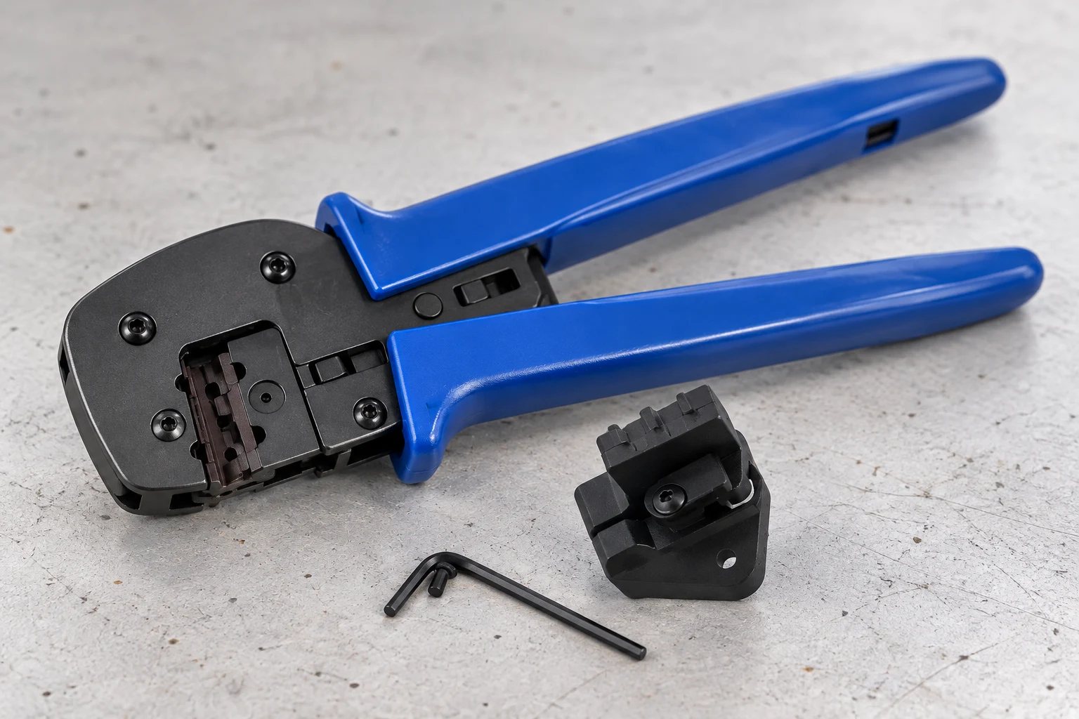
Separate three questions: Which conductor sizes are advertised? Which contact geometry does the die support? What documentation accepts that exact tool/contact/cable combination? A product page may answer the first question clearly and leave the others for technical confirmation.
MOES lists a PV-FMC4 solar crimping tool and a PV-XMC4 precision crimping tool. Use the exact product identification in an inquiry and request confirmation for your proposed contacts and cable. These are starting points for selection, not evidence that either tool is approved for every connector sold under an “MC4-compatible” description.
Build a short controlled work instruction from the actual component documentation. It should identify the cable, contact, housing, seals, tool, die, and inspection method. Include document revisions and sample photographs of accepted results where the manufacturer provides them. This avoids a workshop relying on a remembered procedure from a different connector family.
Inspect the tooling according to its manufacturer’s requirements. Check for damage, contamination, loose components, and worn forming surfaces. Confirm that maintenance and calibration or verification records are current where required. A ratchet release can indicate completion of a stroke; it cannot independently prove that the correct die or contact was selected.
Prepare a clean, dry work area with clearly separated component batches. Protect loose contacts and mating interfaces from grit, moisture, and damage. Do not return unidentified parts to an approved bin. If components become contaminated, follow the manufacturer’s disposition instructions rather than improvising cleaning chemicals or lubricants.
Before production, make trial samples with the actual planned materials. Have a competent reviewer compare them with the specified acceptance criteria, including any required measured or destructive tests. Keep the accepted sample record alongside the tool and component identities. This gives operators a defined reference for the batch.
Check the contact and housing identities before cutting cable. Confirm that any gland, seal, or other component that must be fitted before termination is handled in the sequence specified by the connector instructions. The sequence varies across products, so do not treat a general online demonstration as the procedure for your assembly.
Use the specified stripping method and length. Inspect the conductor for missing, cut, nicked, or displaced strands and inspect the remaining insulation for damage. Do not shorten the strand bundle, fold it over, tin it, or alter it to make an unsuitable contact appear to fit. Stop and resolve an incorrect cable/contact combination.
Load and orient the contact as required for the selected tool and die. Place the prepared conductor in the prescribed position and complete the tool’s operating cycle. Keep insulation and stray strands out of areas where the instructions do not permit them. The operator must be able to identify correct positioning before compression makes the assembly permanent.
If the contact shifts, the tool behaves abnormally, or the result differs from the accepted sample, isolate the affected work. Do not automatically apply a second squeeze or a different die to rescue a questionable termination. Rework is acceptable only where the manufacturer provides an approved method; otherwise replace the affected contact and prepare a fresh cable end.
This is the useful inspection point for exposed contact defects. Compare the crimp shape, strand containment, conductor position, and insulation relationship with the relevant drawing or acceptance example. If measured crimp dimensions are required, use the specified method and limits. Record the result before the housing conceals it.
A casual pull may reveal a grossly loose termination, but it is not equivalent to a specified pull-force test. Formal sampling needs a defined method, suitable equipment, acceptance limits, and a clear rule for what happens after a failure. Do not invent a universal force value for unrelated contact families or conductor sizes.
Install and retain the contact, seal, and gland according to the connector instructions. Verify contact retention using the prescribed method and tighten components using the required tooling and torque where specified. Do not infer correct sealing from how tight a nut feels. Excess tightening can create damage rather than improve the assembly.
The cable outside diameter must suit the selected sealing arrangement. A suitable copper cross-section does not establish that fit. When the assembly is complete, preserve polarity identification and protect its mating interface until it is installed. Review the companion solar connector compatibility checklist before selecting the counterpart.
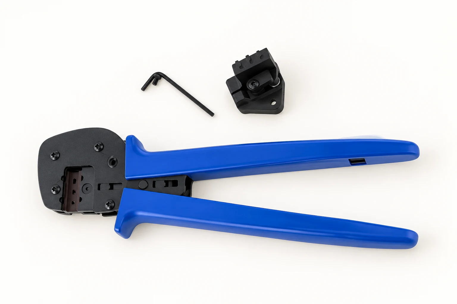
The table below translates the workflow into review points. It deliberately avoids generic strip lengths, torque values, or pull-force limits because those must match the actual approved assembly.
| Checkpoint | What to verify | Action if uncertain or defective |
|---|---|---|
| Incoming components | Correct cable, contact, housing, seal, and batch identities | Segregate unidentified or substituted parts |
| Prepared conductor | Specified strip length and intact conductor strands | Prepare a fresh end using the approved method |
| Tool setup | Approved die, orientation, locator, and tool condition | Stop production until setup is confirmed |
| Completed crimp | Required geometry, strand position, and specified dimensions | Reject or use only a documented rework route |
| Mechanical test | Specified sample method and acceptance limit where required | Apply the batch containment and investigation rule |
| Housing assembly | Contact retention, complete assembly, and correct gland fit | Hold the lead for technical disposition |
| Finished lead | Identification, polarity record, protected interfaces, and inspection result | Prevent shipment until the record is complete |
These are process controls rather than a certification test plan. Define the applicable inspection and sampling requirements with the responsible technical team before production begins.
A neat exterior can conceal an internal problem. Conversely, a rejected visual condition may need no further testing before the part is excluded. Keep those decisions distinct. An inspection plan should state which defects cause immediate rejection and which measurements or tests establish acceptance for the remaining samples.
Sandia’s PV connector research program investigates fielded connector performance and failure mechanisms. That work supports treating connector reliability as a lifecycle issue involving design, installation, exposure, and maintenance. It does not justify a universal claim that a single workshop check guarantees years of field performance.
For deployed equipment, qualified teams may use documented electrical inspections and thermal surveys as part of maintenance. Thermal findings require operating context and further investigation; an apparently normal image is not proof that every termination is sound. Never use operating equipment as an informal test bench for an unqualified crimping process.
Record the cable and contact lots, tool and die identification, operator, work-instruction revision, production date, sample results, and finished-lead identifiers. If a defect appears later, these details let the team identify potentially affected assemblies. A generic “QC passed” sticker cannot perform that tracing function.
Define what triggers a new first-piece approval: a contact or cable change, a die replacement, a changed tool setting, a revised instruction, or another process change identified by the technical team. Also define how production stops and how the affected batch is isolated after a failed check. Discovering the response rule after shipment is too late.
Buyers ordering preassembled leads should request the same evidence in a proportionate form. State the required connector pair, cable, length, end identification, documentation, sample checks, and substitution controls in the purchase request. Connectors belong within the wider solar tool and assembly workflow; related inverter datasheet checks and system sizing information help define the equipment and circuit that those leads must serve.
TED-Ed’s explanation of photovoltaic generation provides background for the electrical source connected to these leads. It is useful orientation for purchasing teams and trainees; product-specific crimping instructions and electrical safety training remain separate requirements.

Watch “How do solar panels work? – Richard Komp” from TED-Ed.
For a neutral training reference, IREC’s photovoltaic laboratory guidance treats conductors, module interconnects, connectors, and assembly tools as practical training materials. A video alone is not evidence that an operator has demonstrated the required assembly skills.
Use the tool and die specified or accepted for the exact contact and cable. Ordinary pliers do not establish the controlled geometry or documented process required for a qualified termination.
No. The conductor range is only one condition. Confirm the contact geometry, die profile, positioning method, and the connector manufacturer’s acceptance of the combination.
Use the values in the current instructions for the exact connector, contact, cable, and gland. There is no single value that should be applied to all solar connectors.
No. It may expose a gross defect but does not replace specified inspections or a defined pull-force test. Use the applicable test method and acceptance criteria.
Do not improvise rework. Follow an explicit approved rework procedure if one exists; otherwise replace the affected contact and prepare a new cable end.


OTHER SMART DEVICES
Jun 13,2026
OTHER SMART DEVICES
Jun 12,2026
TUYA SMART HOME PRODUCTS
Jun 12,2026
 +86 137 3639 3028