

by NOVA

Sep 02, 2026
Before anyone lands wires from a 3 way motion sensor light switch wiring diagram, freeze traveler and common identity, which location hosts the motion unit, neutral and ground status, load type, occupancy versus vacancy mode, and labeled topology photos on one signed sheet. This page is for electricians, integrator coordinators, and distributors packing multi-location hallway, stair, and garage jobs—not a DIY wire-by-color tutorial and not a standalone home motion-sensor placement guide.
You will get the copper and mode fields that DIY diagram pages skip, plus a signed checklist that stops wrong kits from shipping. When the sheet passes, browse the smart switch pillar for wall-switch families, or read motion sensor installation for homes project inputs when the job is a wireless presence sensor rather than a 3-way wall switch.
Document the multi-location circuit before anyone trusts a color diagram. Search results for a 3 way motion sensor switch wiring diagram are packed with step-by-step wire landings and brand PDFs; those pages rarely force crews to archive which screw was common, which box will host the sensor, or whether the lamps are LED loads below a sensor’s minimum.
A project-input sheet turns that noise into order gates. Distributors can attach the same sheet to sample pulls so warehouse picks match the topology the field actually photographed.
Mark the common conductor at each box before any wire leaves a screw. On a mechanical 3-way switch, the common terminal is usually the darker screw; Traveler wires land on the two brass terminals. One common carries line power into the first location; the other common carries the switch leg out to the load—so swapping a traveler into a common screw breaks the circuit logic.
Wire color is not a reliable map. Field communities repeatedly warn that electricians grab whatever jacket is handy, and that memory fails within minutes after a plate comes off. Photograph both boxes with wires still on the screws, including screw color, then tag the common with tape before disconnect.
| Field | What to write | Why it matters |
|---|---|---|
| Box A common | Line / load / unknown — photo ID | Pivot for that location |
| Box B common | Line / load / unknown — photo ID | Opposite end pivot |
| Traveler pair | Colors + which cable (e.g., 14/3 red/black) | Multi-location path |
| Ground | Present / bonded / missing | Safety path for devices |
| Label owner | Who marked commons before disconnect | Archive accountability |

Record the Motion unit location—which physical box will host the sensor—and which kit architecture the datasheet requires. Many hybrid installs place the electronic sensor where constant line power is available and leave a mechanical 3-way at the remote end. Other master/companion families place line and load at the master and repurpose a traveler as a communication path—so a “put the sensor at the top of the stairs” rule fails when the product diagram says otherwise.
Also freeze whether the job needs one motion sensor plus a compatible remote, or a matched dual-sensor kit. Two independent sensors on a standard traveler pair without a shared protocol can fight each other and leave lights stuck on or dead.
Log whether a Neutral / grounded conductor is present in each switch box before ordering electronic motion controls. Educational summaries of NEC 404.2(C) explain why many lighting switch locations that feed bathrooms, halls, stairs, and habitable rooms are expected to provide a neutral so smart switches, dimmers, and occupancy sensors can draw continuous power—subject to Code exceptions and local adoption. Confirm the adopted edition with the project’s electrician or AHJ; treat the citation as a planning reminder, not a stamped inspection result.
Community wiring wikis for automated 3-way switches make the same practical point: a neutral plus a traveler is the common requirement, and low-wattage LED or fluorescent loads usually cannot lean on old no-neutral leakage tricks. If the sheet shows neutrals only at the fixture, escalate a pull or pick a datasheet that explicitly supports the no-neutral path for that load class.
Ground stays on the same row. Bond device grounds to the house ground; do not invent a bootleg neutral on the ground path to “make the sensor wake up.”
Write the LED load type and other lamp/driver classes beside every motion-switch SKU candidate. Electronic sensors often publish maximum wattage by load family and sometimes a minimum load; LED hallway strips that sit under that minimum flicker, ghost, or refuse to turn off cleanly.
Capture fixture count, approximate wattage, dimming vs on/off, and whether any ballast or LED driver is known to be picky with electronic switches. If the datasheet lists an LED compatibility table or a bypass accessory, archive that part number on the sheet before the truck rolls.
Important: Treat LED flicker after a 3-way motion swap as a load-compatibility and connection check first—loose travelers and undersized LED loads are common culprits—before blaming the sensor firmware.
Record whether the space needs Occupancy mode (auto-on/auto-off) or Vacancy mode (manual-on/auto-off) behavior before anyone programs timeouts. Energy-code education digests describe occupant sensing controls that turn lights off or down within about twenty minutes after a space is vacated, and they describe manual-on grace windows measured in seconds. Where a project must stay manual-on, the sheet should also note that occupants must not be able to flip the device back to auto-on.
Hallways and stair landings often want occupancy so hands stay free on the rails. Closets, offices, or code-sensitive rooms may require vacancy. Write the required mode, timeout target, and who is allowed to change it after commissioning.
Freeze Topology photos and fields before purchase orders move. Professional smart-home wiring guidance stresses labeling cables and documenting paths and schemes so the next crew is not guessing; the same discipline applies to a 3 way occupancy sensor switch wiring diagram job even when the walls stay closed.
From the field: SmartThings contributors urge photographing existing wiring—including which screws held which wires—because jacket color is not guaranteed and memory quietly “corrects” the mess into a tidy wrong story. (source)
| Input | What “done” looks like |
|---|---|
| Common IDs (both boxes) | Tagged + photo with screw color visible |
| Traveler pair | Colors and cable noted |
| Motion-unit location | Box labeled; kit type named |
| Neutral status | Present / absent / fixture-only — verified by |
| Ground | Bonded / missing — action noted |
| Load class | LED / CFL / incandescent / mixed + approx. watts |
| Mode | Occupancy / vacancy + timeout owner |
| Dual-sensor decision | Single sensor + remote / matched kit / N/A |
| Licensed work owner | Named electrician or integrator |
| Sign-off | Date + buyer + field lead |
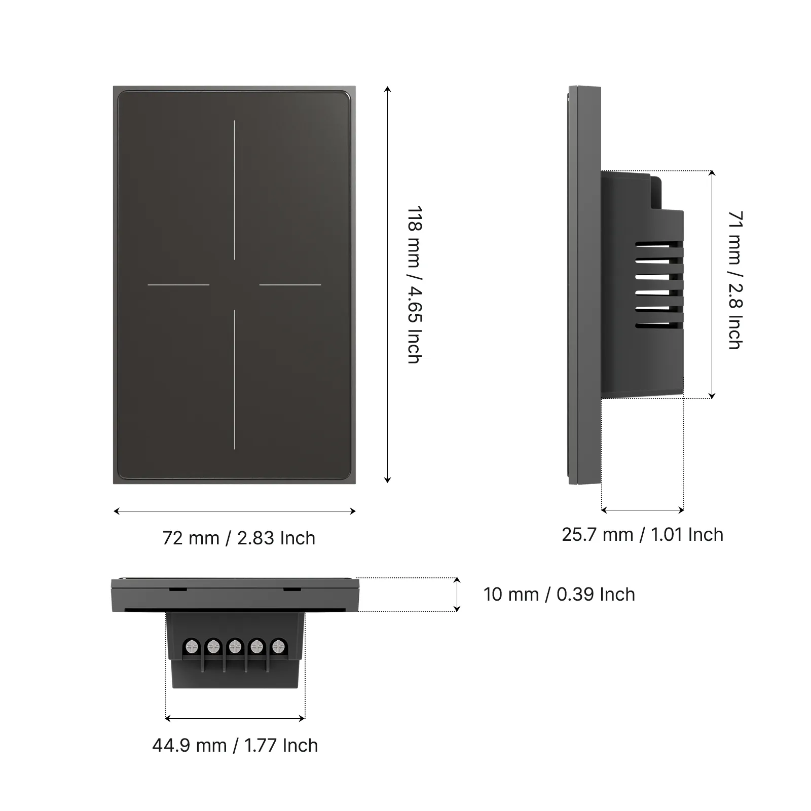
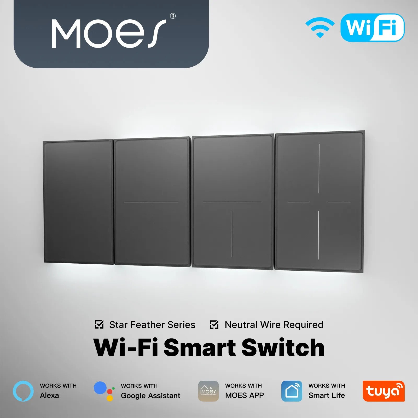
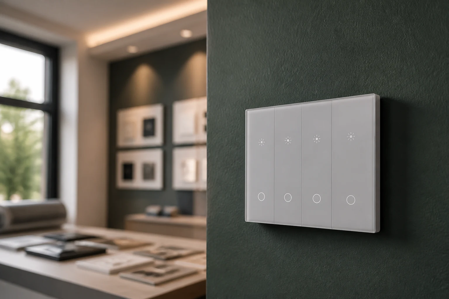
Browse MOES wall-switch families only after the multi-location motion-switch inputs above are signed. The MOES Tuya WiFi Star Feather Series US Switch (models WS-SF-US1/2/3/4) is a US-format Wi-Fi wall switch family rated 90–250V AC at up to 10A per gang with a 10A total, built as a neutral-wire product class in MOES collection evidence. Star Feather US fits channel jobs whose sheet already shows matching US form factor, neutral, Wi-Fi path, and load headroom—and whose next hardware need is a smart wall switch pathway rather than a dedicated PIR occupancy wall-sensor SKU.
Do not treat Star Feather as proof that every multi-location motion diagram is satisfied. If the sheet calls for a line-voltage occupancy/vacancy wall sensor with traveler terminals, keep that SKU class on the motion-switch row and use Star Feather only for adjacent smart-switch scopes that clear the same copper gates. Light Mode and Scene Mode on Star Feather cannot run simultaneously—capture the intended mode on commissioning notes when that family is in scope.

When the signed sheet points to wireless presence sensors instead of a 3-way wall switch, use the motion sensor installation for homes inputs page for placement and power-class fields. For broader wall-switch browsing after copper clears, stay on the Smart switch pillar at smart switch or contact MOES with the archived photos attached.
Freeze common vs traveler IDs at both boxes, motion-unit location and kit type, neutral and ground status, load class, occupancy vs vacancy mode, topology photos, and a named licensed-work owner before anyone lands wires or ships hardware.
Look for the darker common screw on the existing device, then confirm with a proper meter workflow under a safe lockout procedure. Tag that conductor before disconnect; do not trust jacket color alone.
Most electronic sensors need a neutral so the detection hardware stays powered. Log neutral presence as a hard field; if the box lacks one, escalate a conductor pull or choose a datasheet that explicitly supports no-neutral operation for the planned load.
Follow the chosen product diagram. Many hybrid kits want the sensor on the constant-line end; some master/companion kits want line and load at the master. Write the decision on the sheet instead of guessing from hallway traffic alone.
Only when the manufacturer ships a matched dual-sensor or master/remote protocol for that purpose. Two unrelated sensors on a classic traveler pair can conflict.
Occupancy turns lights on automatically with motion and off after vacancy timeout. Vacancy requires a manual on and still auto-offs when the space empties. Record the required behavior before programming.
Low-wattage LED loads can sit under a sensor’s minimum load, and loose traveler or line connections can mimic the same symptom. Log lamp wattage and re-check terminations before swapping firmware assumptions.
This page owns multi-location wall-switch wiring-diagram inputs. Standalone sensor placement, coverage, and false-trigger fields live on the motion sensor installation for homes project inputs article.


OTHER SMART DEVICES
Jun 13,2026
OTHER SMART DEVICES
Jun 12,2026
TUYA SMART HOME PRODUCTS
Jun 12,2026
 +86 137 3639 3028