

by NOVA

Sep 03, 2026
Successful 3 way motion sensor switch installation starts with a signed install sheet—not with improvising wire colors on the day crews open the boxes. This page is the install-day input pack for multi-location hallway, stair, and garage jobs.
It covers which box hosts the sensor head, what device sits on the companion location, how cutover is sequenced, which occupancy or vacancy settings are approved, what the commissioning test must prove, and who owns callbacks after leave-site. Label-and-document practice for that archive follows trade guidance such as CEDIA — The Ultimate Smart Home Wiring Guide.
For traveler and common identification matrices used when reading a wiring diagram, use the sibling 3-way motion sensor light switch wiring diagram project inputs page. Licensed electrical work stays with qualified people; this article documents the gates that keep kits and tickets aligned.
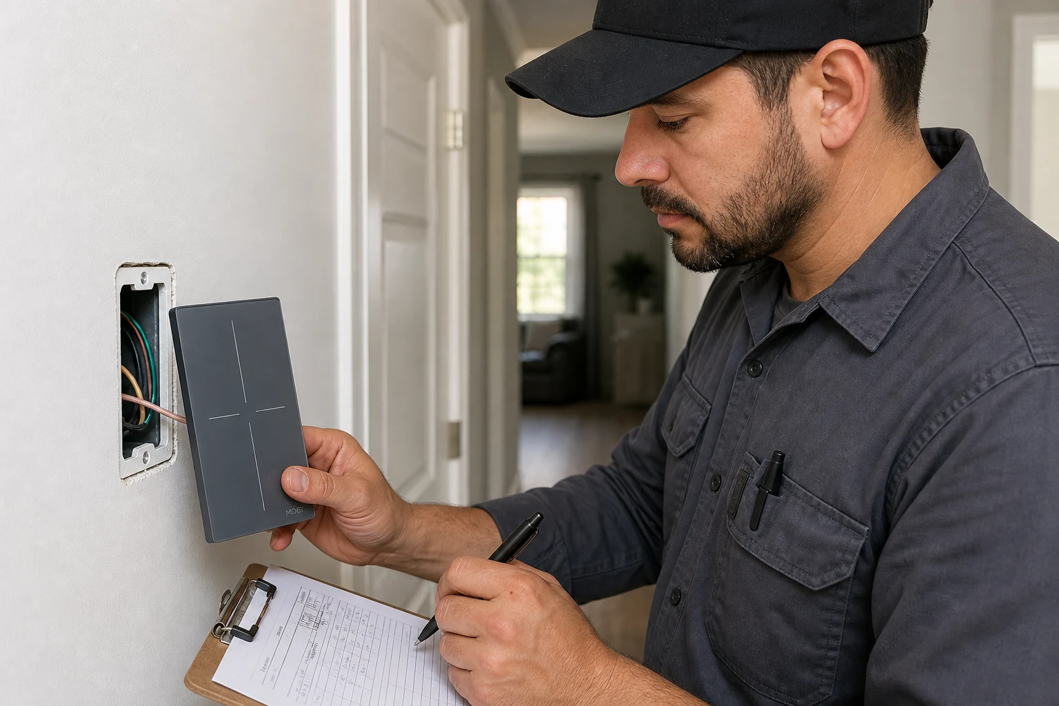
Freeze the install gates before anyone cuts power or lands a motion sensor on a multi-location circuit.
Search results are full of screwdriver tutorials. Hallway and stair jobs still fail when the kit, the sensing location, the second-end device, and the leave-site test were never written down.
A 3 way occupancy sensor switch or 3 way motion sensor smart switch changes how the second location behaves. Many kits allow only one sensing head. The other end must be a matching companion or an approved mechanical three-way—not a second identical sensor by default.
Documenting those decisions up front keeps distributors from shipping the wrong pair. It also keeps installers from discovering the conflict after drywall dust is already on the floor.
Treat the sheet as a project archive, not a substitute for the manufacturer diagram. When copper identity for a diagram sheet is still open, finish that work on the wiring-diagram inputs sibling first, then return here for install-day sequencing.
Log the physical box that will hold the Sensor head / master sensor so coverage and power topology both match the chosen kit.
The Sensor head / master sensor is the wall unit with the motion “eye.” Coverage usually wants a clear view of the traffic path—bottom of a stair, middle of a hall, or the doorway people actually use.
Topology often wants the head where the datasheet expects line, load, or a combined master location. Those two pressures do not always point at the same box. Record both the preferred coverage box and the datasheet-required topology before anyone orders hardware.
| Decision field | What to write on the sheet | Why it matters on install day |
|---|---|---|
| Coverage box | Which doorway/landing the lens must see | Avoids heads that face a wall or HVAC plume |
| Topology box | Line, load, or datasheet “master” location | Prevents kits that cannot live in the pretty box |
| Conflict note | Coverage ≠ topology? Who decides? | Forces a signed choice before cutover |
| Dual-head request | Owner wants sensing at both ends? | Triggers companion-kit check in the next section |
If the owner wants detection from both ends of a long hall, do not silently order two standalone sensors. Mark the dual-head request on the sheet and resolve it with the companion rule below.
Record what sits on the second location—manufacturer Companion / remote switch, approved mechanical three-way, or a datasheet-allowed dual-sensor kit—before the PO leaves the warehouse.
Many 3 way sensor switch families allow only one sensing switch on a multi-location circuit. The other end becomes a Companion / remote switch or accessory device, or sometimes a standard mechanical three-way that the instructions still allow.
Community threads are full of crews who replaced both ends with the same occupancy SKU and then watched one location click while the light stayed dead. That failure is a documentation miss, not a mystery.
Important: If the sheet does not name a companion type, treat “two identical motion sensors” as blocked until the datasheet explicitly allows a paired dual-sensor architecture. Source: manufacturer multi-location notes and community dual-sensor failure threads summarized in research (see SmartThings Community — Automated 3-way Switches (US)).
Write the companion SKU family, or “mechanical 3-way allowed,” next to the sensor-head SKU. If the second location must remain a plain toggle for aesthetics, confirm the motion unit’s instructions still support that pairing. If they do not, change the kit before install day—not after the first callback.
Capture the power-isolation plan, survey photos, Neutral conductor gates, and restore order before crews open either box.
Install day is a sequence, not a pile of wire nuts. On the sheet, list which breaker is locked out, who verifies dead with a tester, and which box is opened first.
Photograph both locations with conductors still on the screws—including screw color—then tag the conductors the diagram sheet already identified. Educational summaries of neutral planning for electronic lighting controls explain why many electronic sensors expect a Neutral conductor or an approved ground return in the wallbox.
Log Neutral conductor presence or absence as a hard gate without turning this page into a traveler pin table. For educational switch-path fundamentals behind that gate, see SparkFun — Button and Switch Basics.
From the field: Crews who skip screw photos spend the callback guessing which black was common. Keep the photo set with the signed sheet. Source: SmartThings Community — Automated 3-way Switches (US).
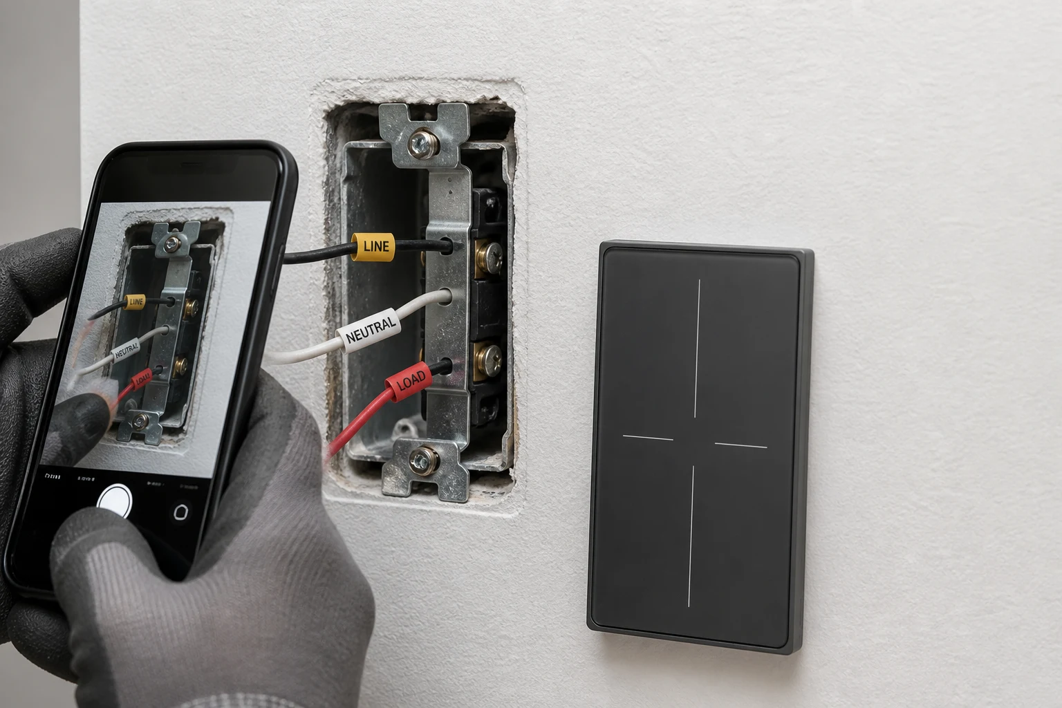
Restore order matters too. Note whether the sensor needs a warm-up or calibration window after power returns, whether the companion must be tested before the wall plates go on, and who is allowed to re-energize the circuit. If any field is blank, the job is not ready for cutover.
Sign occupancy or vacancy—and the timeout target—before anyone programs dials or app defaults at leave-site.
Occupancy mode turns lights on automatically when motion is detected and off after a vacancy timeout. Vacancy mode waits for a manual on, then still turns lights off after the timeout.
Federal lighting-controls guidance treats those as different energy strategies. Vacancy can save more in daylit rooms where people might leave lights off. Occupancy fits spaces where people expect an automatic greeting.
Energy-code education materials often discuss timeout caps around twenty minutes for many space types. Longer timeouts can erase savings even when the hardware “works.” See DesignLights Consortium — Lighting Controls Best Practices for occupancy versus vacancy strategy and timeout education.
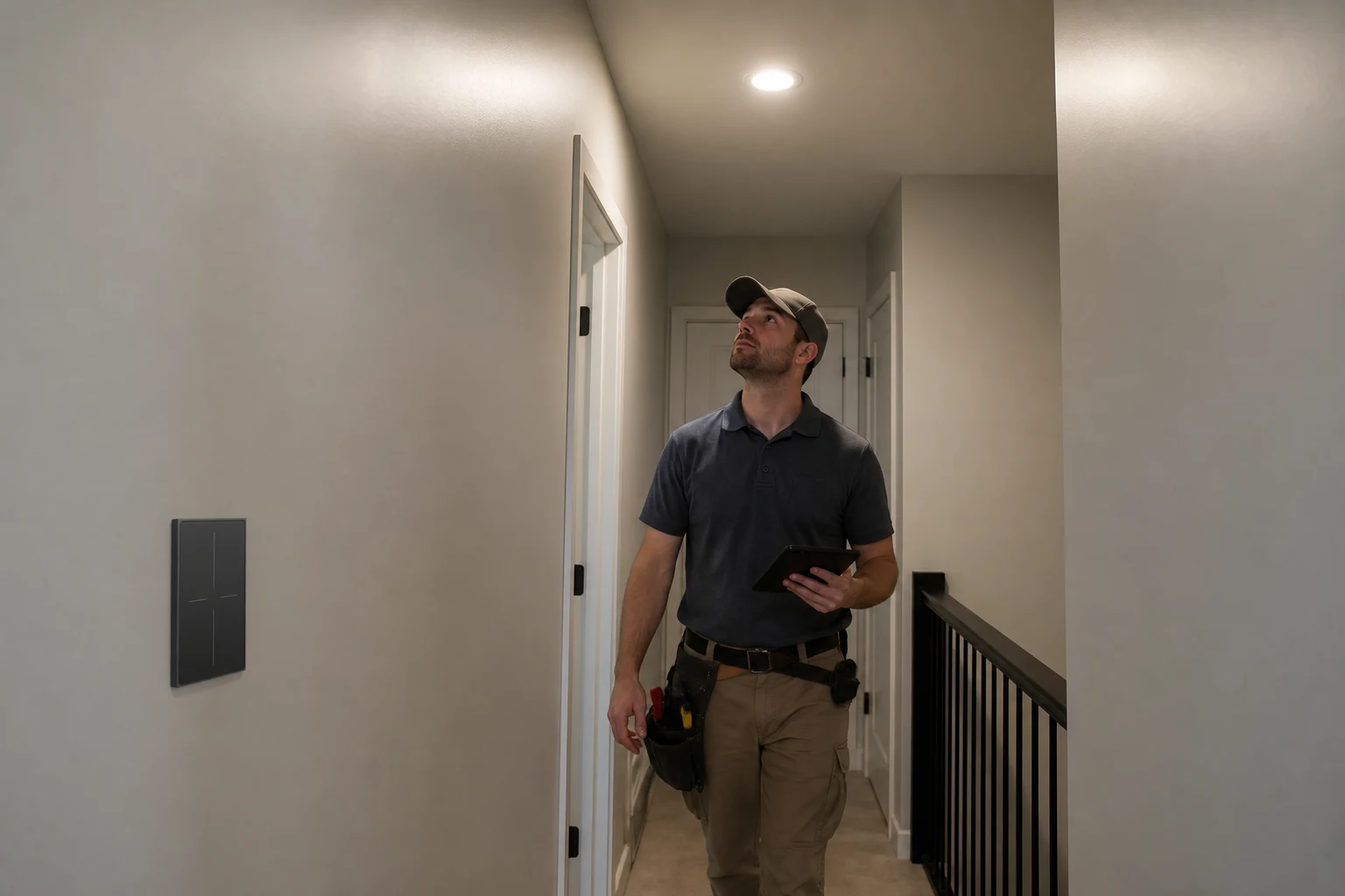
Write three lines on the sheet: mode (occupancy or vacancy), timeout target, and who approved it. If a local energy rule or owner preference conflicts with the default dial, the signed preference wins for programming—and the callback owner knows what “correct” means.
Prove the install with a short, signed test script: settle time, occupied walk-test, vacant clear, and companion override.
Wiring continuity is not the whole job. Electronic sensors often need a brief settle or warm-up window after power-up before automatic detection is trustworthy.
PIR education materials commonly describe a short motion-free snapshot period, and wall-switch manuals may state their own calibration. Put that wait on the script so nobody “fails” a sensor that is still waking up. Independent PIR warm-up context: SparkFun — PIR Motion Sensor Hookup Guide.
Then walk the coverage path the sheet promised. Confirm auto-on or manual-on behavior matches the signed mode. Stay still long enough to catch false-off risk in rooms where people sit.
Clear the space and confirm the light times out. Operate the companion location to prove the second end still controls the load. If HVAC vents or open doorways cause false-on during the test, adjust sensitivity or lens mask per the datasheet and re-run—not “ship and hope.”
Name who owns false-trigger, no-light, and “never know if it is on” tickets before the crew leaves.
Integrators joke that motion on three-ways feels unpredictable when mode, timeout, and companion behavior were never handed off. The sheet should list a primary callback owner, a secondary contact, and the time window for first response.
Attach the signed mode, timeout, test results, and photo set so the ticket does not restart as a wiring debate.
| Install-day field | Value to freeze | Owner initials |
|---|---|---|
| Sensor-head box + coverage note | ||
| Companion device type / SKU | ||
| Breaker ID + isolation verifier | ||
| Neutral / ground gate (pass/fail) | ||
| Occupancy or vacancy + timeout | ||
| Test script result (pass/fail + time) | ||
| Callback primary / secondary | ||
| Sheet signed date |
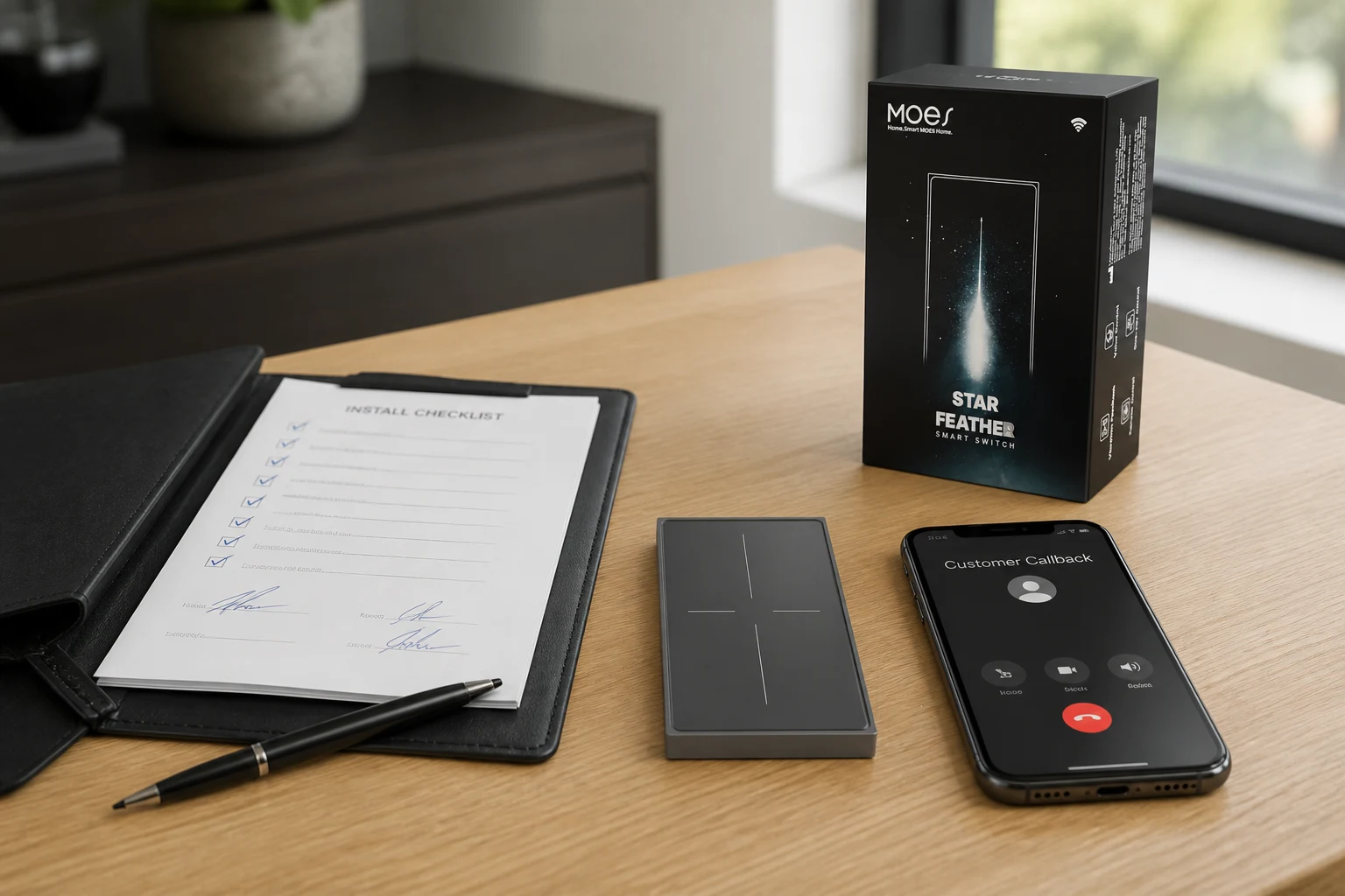
If the owner later asks for dual sensing heads, reopen the companion field—do not “just add another sensor” on a callback visit.
Browse MOES wall-switch families only after the multi-location motion-switch install inputs above are signed.
The MOES Tuya WiFi Star Feather Series US Switch (MOES Star Feather US model family WS-SF-US1/2/3/4 on the product page) is a US-format Wi-Fi wall switch listed at 90–250V AC, 50/60Hz, with a maximum current of 10A per gang and 10A total on that page. It is a bounded pathway for related smart multi-location control when the signed sheet calls for a neutral-wire Wi-Fi wall switch.
Do not use that pathway when the sheet requires a dedicated PIR occupancy wall-sensor SKU, a no-neutral special, a non-Wi-Fi mandate, a load above those page totals, or an EU format device.
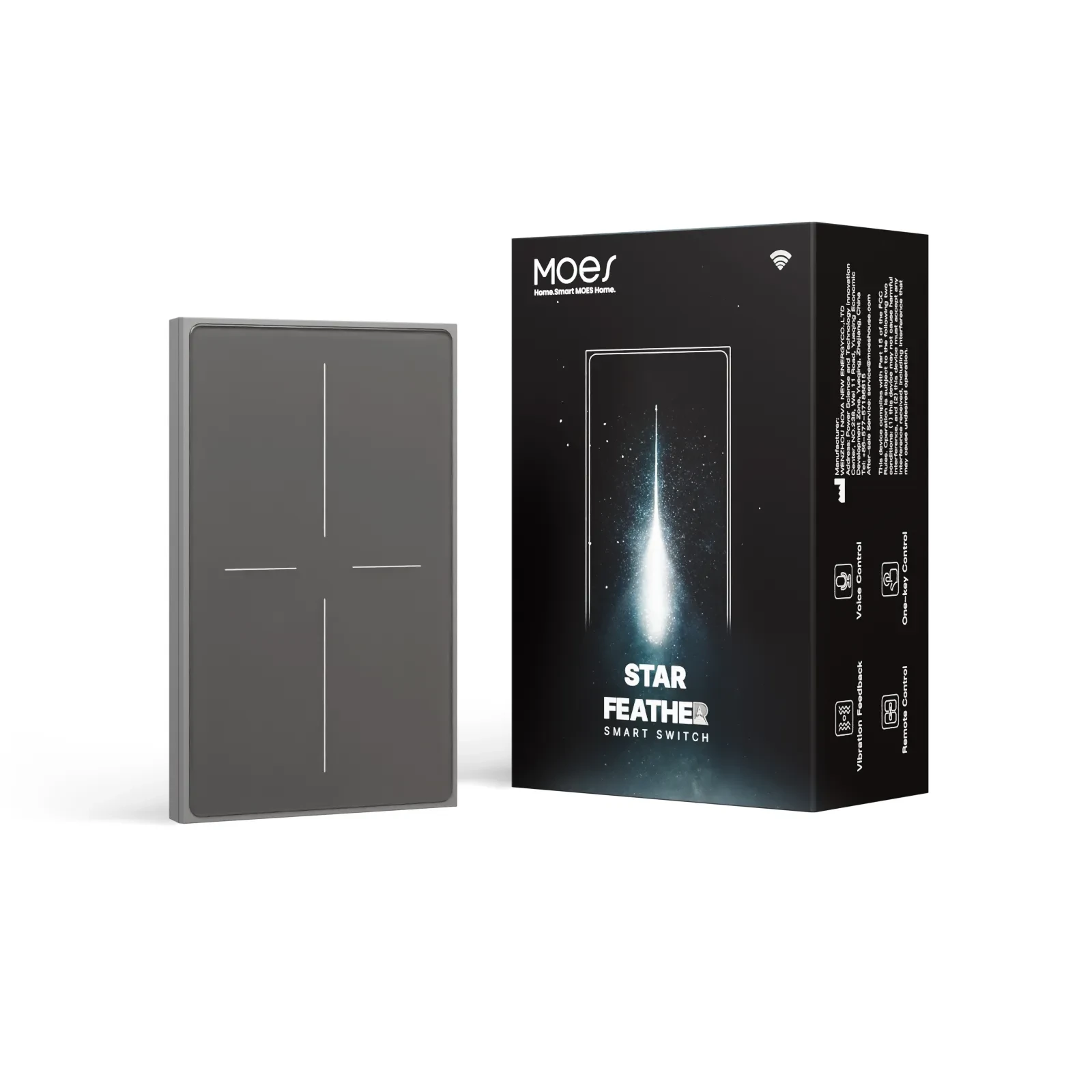
Do not treat Star Feather as proof that every 3-way motion sensor kit is satisfied. If the sheet still needs traveler and common matrices for a diagram, finish that on the wiring-diagram project inputs page. For broader wall-switch families, start at the smart switch pillar, then Contact Us after the install sheet is signed.
Freeze sensor-head box and coverage note, companion device type, cutover and isolation fields, neutral/ground gate, occupancy or vacancy plus timeout, commissioning test results, and callback ownership on one signed sheet.
Choose the box that can see the traffic path and still match the datasheet’s line/load or master topology. If those conflict, write the decision on the sheet before ordering.
Only when the kit explicitly supports paired dual-sensor architecture. Many families allow one sensing head plus a companion or mechanical three-way; two identical standalone sensors often conflict.
Use the manufacturer companion/accessory the datasheet names, or a mechanical three-way only if the instructions still allow it. Record the SKU family on the sheet next to the sensor head.
Occupancy is auto-on/auto-off. Vacancy is manual-on/auto-off. Sign the mode and timeout so programming and callbacks share one definition of “correct.”
Settle/warm-up wait, occupied walk-test for the promised coverage path, vacant timeout clear, companion override, and any sensitivity or mask adjustments made during testing.
Name a primary and secondary owner, attach the signed mode/timeout/test pack, and keep that handoff with the project archive so false-trigger tickets do not restart as wiring arguments.
This page owns install-day sequencing and commissioning fields. The sibling wiring-diagram inputs page owns traveler/common identification and topology photo fields for diagram work—use both without duplicating each other’s tables.


OTHER SMART DEVICES
Jun 13,2026
OTHER SMART DEVICES
Jun 12,2026
TUYA SMART HOME PRODUCTS
Jun 12,2026
 +86 137 3639 3028