

by NOVA

Sep 17, 2026
Compare the jobs before you compare the boxes: a sound solar inverter vs charge controller decision starts from the fact that these two devices do different work, and that a battery-based design needs both jobs done somewhere. The controller sits on the panel side of the battery and settles how much array current reaches the battery bank and on what charge profile. The inverter sits on the load side and settles what voltage, frequency and short-term headroom the site’s equipment actually sees.
So the live choice is whether those two jobs live in two enclosures or one, and a brief that names only one device usually hides an incomplete kit. What follows separates the two jobs, maps them onto the array and the loads, and turns the one-box-or-two question into something a channel buyer can settle from project facts.
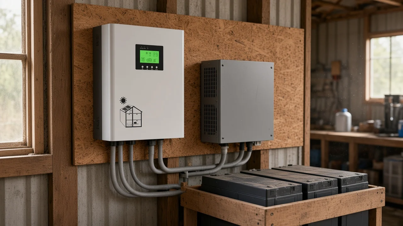
It decides how many enclosures carry two jobs, not which device is better. Industry guidance on battery-based systems is blunt about it: almost every photovoltaic plus storage application needs both an inverter/charger and a solar charge controller, and the one stated exception is a site whose loads all accept DC and whose array can charge the bank reliably through the whole year.
The confusion is easy to inherit. Installer training material describes the regulator as an extra circuit found inside inverters for battery systems, which reads as though buying the conversion stage settles the charging question too.
| Job in a battery-based system | Device that owns it | What it settles | What it cannot do |
|---|---|---|---|
| Charging the bank from the array | Solar charge controller | Charge current, charge voltage and the stage profile the bank sees | Produce an AC waveform for any load |
| Holding the array near its best operating point | MPPT charge controller | How much of the array’s available power reaches the bank in weak light | Convert DC into AC |
| Blocking reverse flow after dark | Solar charge controller | Whether current can drain back into the modules at night | Feed a heavy AC load directly |
| Converting DC into AC | Solar inverter | Output voltage, frequency, continuous power rating and surge rating | Regulate a battery charge profile on its own |
| Refilling the bank from the grid or a generator | Inverter/charger | Whether an AC source can charge the battery at all | Track an array with no built-in tracker |
| Moving loads between sources | Transfer switch inside an inverter/charger | Whether the site rides through a change of source | Anything on the DC array side |
A supplier explainer puts the design rule plainly: where a system needs both battery charging control and AC power output, both functions must exist somewhere, whether as separate devices or inside one integrated unit. That single line retires the habit of ranking the two against each other.
Position explains most of the difference, because each device only touches the part of the path it was built for. In a DC-coupled system the array feeds the regulator, the regulator feeds the battery bank, and the inverter draws from the bank to serve AC loads.
A government energy department explainer describes the conversion job in one line: an inverter changes the direct current a solar panel generates into the alternating current the grid and ordinary equipment use, with filters shaping the result into a clean repeating sine wave. The same page attaches a conditional worth carrying into a specification conversation, noting that solar-plus-storage systems rely on advanced inverters to run without grid support during an outage if they are designed to do so.
Coupling decides whether a standalone regulator appears in the kit at all. In an AC-coupled system the array goes through a grid-tied inverter first and the battery is charged after inversion by a battery inverter with its own internal regulation, and an independent technical article is direct about the consequence: the standalone MPPT charge controller is not part of that architecture.
Tracking is the second thing position explains. A tracking regulator holds the array near its maximum power point instead of dragging it down to whatever the bank happens to sit at, and that behaviour only exists on the panel side of the storage.
Let the array, the battery bank, the AC loads and the service expectation decide, because each of those pushes the answer a different way. A hybrid inverter combines array tracking, battery charging, inversion and backup transfer inside one enclosure, while a separate pair keeps each job replaceable on its own.
| Project fact | Points to one hybrid enclosure | Points to a separate pair | Why this fact moves the answer |
|---|---|---|---|
| Array sits comfortably inside the hybrid’s stated solar input window | Strong | Neutral | One box removes a whole DC protection group and a second commissioning job |
| Array is expected to grow, or a second array is likely later | Weak | Strong | An external tracker can be added without touching the conversion stage |
| String cannot reach a wall-mounted unit’s minimum DC input | Weak | Strong | A lower-voltage external tracker is the practical way in |
| Very large bank, or unusual voltage, current or temperature demands on site | Weak | Strong | Modular choice lets each job be specified for the site rather than the enclosure |
| Site must charge from a generator or the grid with automatic start and stop | Strong | Weak | Seamless generator handover lives in a combined inverter/charger |
| Buyer wants the cheapest failure to repair | Weak | Strong | Installers point out that swapping a regulator costs less than swapping a combined unit |
| Buyer wants redundancy through duplication | Weak | Strong | Off-grid crews sometimes run two regulators and two inverters so one fault leaves power on |
| Installer hours and enclosure space are tight | Strong | Weak | Fewer cables, fewer breakers and one commissioning path |
One warning belongs beside the cost column. A cottage buyer on r/SolarDIY found the separate route looked cheaper and gave more capacity, and the reply pointed out that both candidate units were single-phase, so equipment needing the higher household voltage could not run from one of them and the breaker panel might have to change.
Usually it does, provided the array fits inside the window the unit’s own page states. An all-in-one hybrid inverter normally carries its own tracker, and practitioners on r/OffGrid say exactly that to anyone worried the internal regulator is marketing language.
Commercial project guidance draws the boundary at the input envelope rather than the idea. It notes that many hybrid inverters include integrated tracking, so a separate regulator is not always required, while external trackers still appear where photovoltaic capacity is higher, where modular expansion or redundancy matters, or where the battery bank carries particular design requirements.
Important: an integrated tracker has a stated photovoltaic input range that cannot be exceeded, and over-sizing the array against it will trip protections or force the unit to clip power — a published sizing reference puts it in exactly those terms, so the array layout has to be checked against that window before the enclosure is chosen.
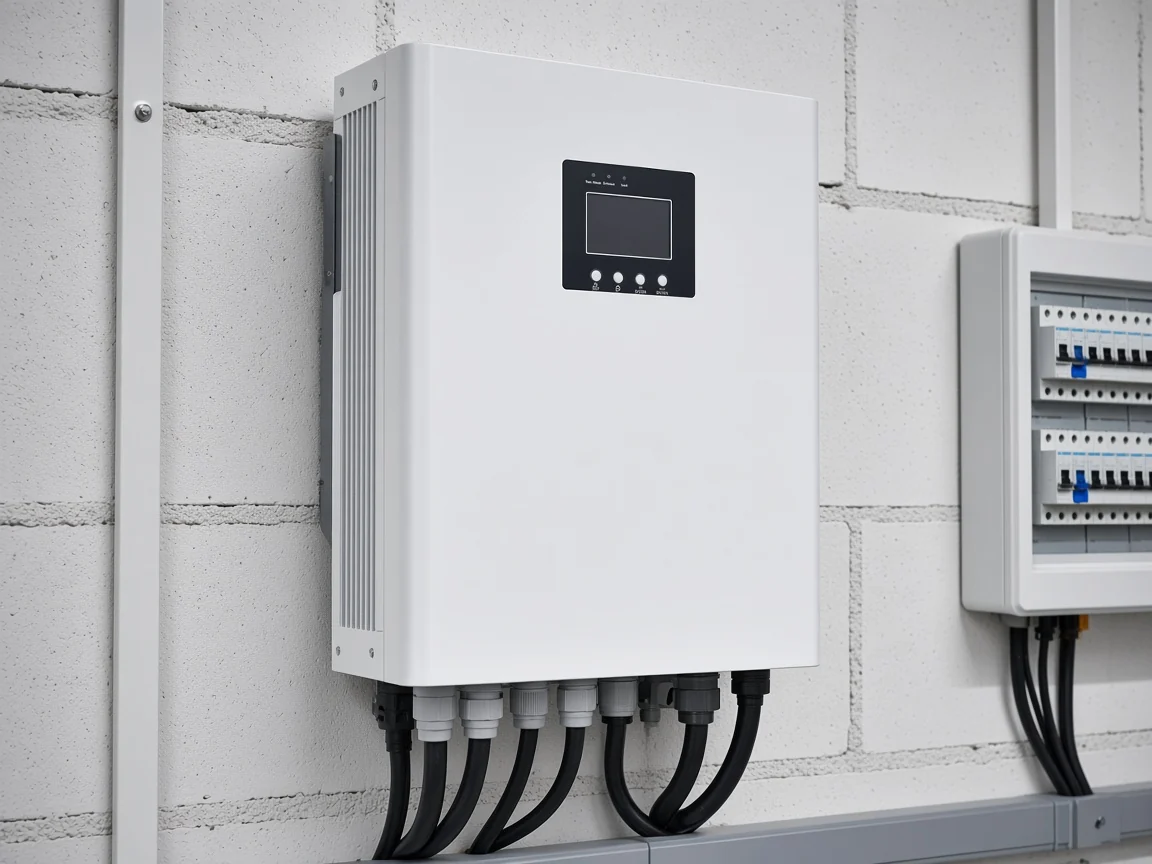
There is one more case worth naming, and it comes from installers rather than datasheets. Where a wall-mounted unit is wanted but the string cannot reach its minimum DC input, a lower-voltage external tracker is how the array gets connected at all. The same thread warns that bolting an extra regulator onto a unit that already tracks can create communication quirks between the two.
Combining the jobs removes a DC protection group and a second commissioning path, and it fixes the photovoltaic input window and the AC output format for the life of the unit. Splitting them adds hardware and choices, and it raises an AC charging question a bare regulator cannot answer.
The charging source is the line quotes miss most often. Practitioners describe the difference exactly that way: a standalone regulator charges from the array only, so grid or generator charging needs an AC-to-DC path, and that path lives inside an inverter/charger.
| Kit line | Separate regulator and inverter | One hybrid enclosure |
|---|---|---|
| DC protection between array and regulator | Its own group of devices | Inside the enclosure, or reduced to its terminals |
| Battery cabling sized for inverter peak current | Its own run, kept short and heavy | Still needed, but to one box |
| Protection group on the battery side | A separate item to specify and fit | Usually folded into the unit |
| AC charging from grid or generator | Needs an inverter/charger; a regulator alone cannot do it | Included where the page states a battery charger |
| Handover between sources | Needs the inverter to provide a transfer function | Included where the page states one |
| Monitoring | Two paths, often two apps | One path |
| Enclosure space and installer hours | Higher | Lower |
| Repair when one job fails | Replace the failed device | Service or replace the whole unit |
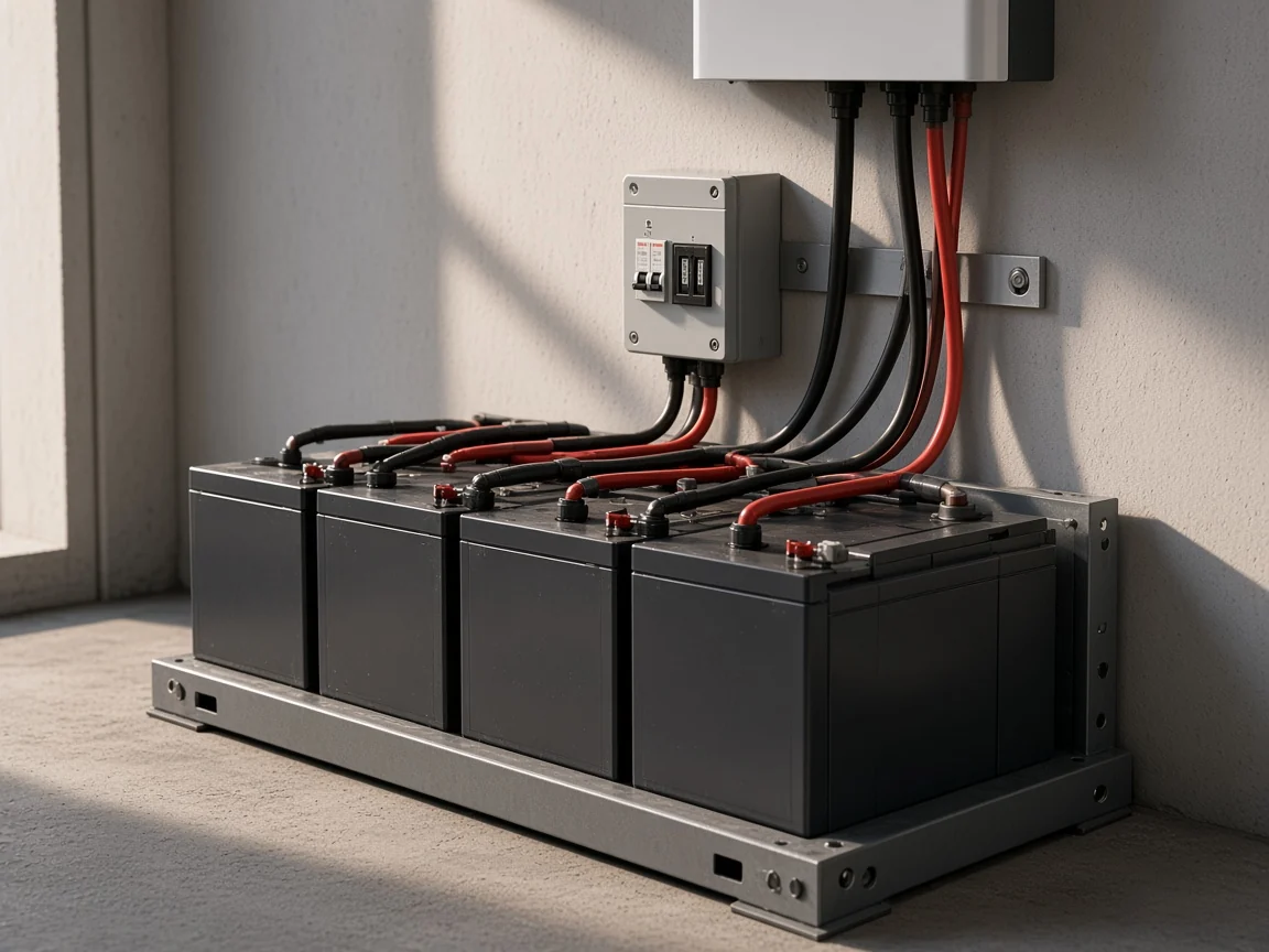
Reference material on off-grid builds adds the operational half of that table. A combined inverter-charger handles inversion, battery charging from a generator or the grid, and solar tracking in one device, and it is what makes automatic generator start and stop seamless; separate components buy independent upgrade paths at the cost of more wiring and more monitoring.
Two neighbouring decisions stay outside the kit question. Sizing arithmetic belongs with the inverter sizing checklist, and the choice between a grid-connected and a standalone architecture belongs with the on-grid and off-grid comparison.
Array voltage and current size the regulator, load power and inrush size the inverter, and the single rating they share is the system voltage of the battery bank. A build guide for battery-based systems states the basis plainly: a regulator is sized on maximum array wattage and on maximum input voltage taken as open-circuit voltage at the coldest expected temperature, while an inverter’s continuous output must exceed simultaneous peak load with a surge rating that covers motor-start inrush.
Cold mornings are what make the voltage ceiling a real limit rather than a formality. An independent module reference puts a 36-cell module at roughly 21V open-circuit at standard test conditions and lists a 72-cell module at 47.3 V, so the module count and string layout decide whether an array clears a given regulator’s input ceiling.
The plate figure also belongs to one test setting. The same reference defines nominal operating cell temperature at 800 W/m2 irradiance, 20°C air temperature and 1 m/s wind over an open back surface, against a plate rating taken at 25 °C, which is why the figure worth asking for is open-circuit voltage at the site’s coldest expected temperature rather than the value printed for test conditions.
| Rating | Sized against | Which device it belongs to |
|---|---|---|
| Maximum photovoltaic input voltage | Array open-circuit voltage at the coldest expected temperature | Solar charge controller, and the tracking stage of a hybrid |
| Maximum charging current | Array current, capped by the battery charge-current limit | Solar charge controller |
| System voltage | The nominal DC voltage of the battery bank | Both devices, and it has to match |
| Continuous output power | Simultaneous peak AC load at the site | Solar inverter |
| Surge capability | Motor-start inrush from compressors, pumps and power tools | Solar inverter |
| Output waveform and AC format | The equipment the site actually runs | Solar inverter |
| Battery chemistry support | The bank that was specified | Solar charge controller, and the charger stage of an inverter/charger |
Where a project is still choosing between a tracking and a switching regulator, the dealer-facing detail sits in the PWM controller selection guide. A PWM charge controller and a tracking unit rarely carry the same input ceiling, so the two are quoted against different array layouts.
Lock the array’s electrical figures, the bank’s limits, the AC load profile and the charging sources, because without them either device can only be guessed at. A sizing reference lists the same inputs: the array’s rated power, its maximum-power voltage, its open-circuit voltage and the module count in series and parallel, plus the battery’s nominal voltage, chemistry and the charge-current limit set by its maker.
| Input to lock | Why it changes the device choice | What an incomplete answer looks like |
|---|---|---|
| Nominal DC voltage of the battery bank | Both devices are ordered against it, and a mismatch makes the pair unusable | A battery count with no nominal voltage |
| Open-circuit voltage at the coldest expected site temperature | It sets the regulator ceiling and the hybrid tracking window | A plate voltage quoted for test conditions |
| Module count in series and parallel | It decides whether a string clears a minimum input or breaches a maximum | An array wattage total with no layout |
| Battery charge-current limit from the cell or pack maker | It caps the useful charging amperage whatever the array could deliver | A capacity figure with no charge limit |
| Simultaneous peak AC load and the worst inrush on site | It separates continuous sizing from surge sizing | A monthly energy total |
| Whether grid or generator charging is required | It decides between a plain inverter and an inverter/charger | A note that mains power is sometimes available |
| Whether the array will grow | It decides whether a fixed tracking window is acceptable | A second phase with no array figures |
| AC output format the site equipment needs | It rules candidate inverters in or out before anything else | A country name on its own |
Those eight lines are enough to price either shape. Without them a supplier is quoting an enclosure against a guess, which is how a kit arrives with the protection and cabling lines missing.
Two field errors follow directly from treating the two devices as interchangeable, and both cost money. The first is wiring the inverter to the regulator’s load terminals as though the regulator feeds the loads.
From the field: a load terminal is a small auxiliary output rather than a feed for a conversion stage, so the inverter belongs on the battery bank with short heavy cables — that is how installers answer this question on r/SolarDIY.
Installers answering this on r/SolarDIY put figures on it: a load output is typically rated around 10A and usually tops out near 20A, while an inverter might pull 100A or more.
The second error is commissioning order. Build guidance notes that most tracking regulators take their voltage reference from the battery, which is why the bank is connected before the array; reverse that order and the regulator has nothing to reference and may refuse to start.
Neither mistake is exotic, and both trace back to the same premise. Once a buyer accepts that the two devices are sequential stages rather than rival products, the wiring and the commissioning order stop being surprises.
For an off-grid solar system brief, two shapes are quotable from live pages today: a separate regulator and inverter/charger pair, or a single hybrid enclosure. Both sit inside the solar charge controller and solar inverter ranges, and every figure below is quoted from the listing it appears on.
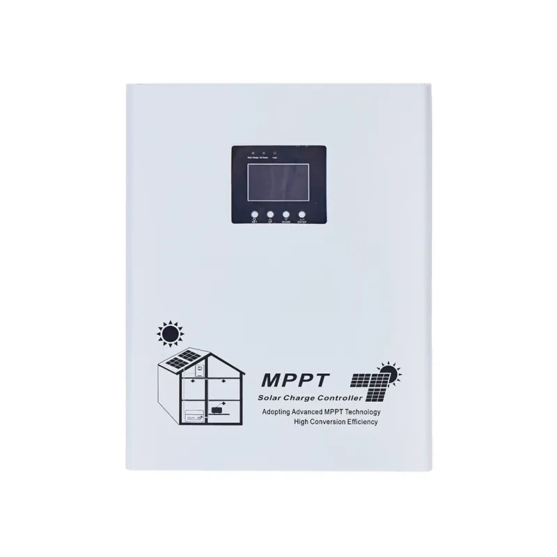
The separate pair is the more flexible of the two shapes, and each listing publishes its own envelope. Read each page on its own terms, because the ranges below belong to the model they are printed on.
The MOES MPPT Solar Charge Controller PV Regulator 30-150A listing states 12/24/36/48V or 48V/96V DC auto detection, a maximum charging current of 30-150A and a maximum photovoltaic input of 180V or 280V, with lead acid, gel, lithium and user-defined battery types.
Paired with it, the MOES low-frequency pure sine wave inverter/charger page states 12/24/48/96V DC operating voltage, single phase 170-275V AC, a 1KW-12KW power range and surge capacity up to 300% peak power.
Where one enclosure is preferred, the MOES WiFi Smart Hybrid Solar Inverter listing states a 48V DC operating voltage, single phase 176-253V output at 50Hz/60Hz, a 4.2KW/6.2KW power range and a built-in MPPT controller rated 80A/100A across a 60V-450V window.
| Page-stated parameter | MPPT regulator listing | Hybrid inverter listing | Low-frequency inverter/charger listing |
|---|---|---|---|
| DC or system voltage | 12/24/36/48V or 48V/96V DC auto | 48V | 12/24/48/96V |
| Charging current stated | 30-150A | built-in MPPT 80A/100A | built-in MPPT 80A/100A |
| Photovoltaic input stated | 180V or 280V maximum | 60V-450V tracking window | not stated on the page |
| AC output | none, a DC device | single phase 176-253V | single phase 170-275V |
| Power range | not applicable | 4.2KW/6.2KW | 1KW-12KW |
| Surge capability | not stated | not stated | up to 300% peak power |
| Battery types stated | lead acid, gel, lithium, user-defined | not stated | not stated |
| Charging from an AC source | no | yes, AC and DC control | yes, inverter/charger |
Two limits belong with the pairing. No rating above carries across to another listing, so a ceiling printed on one page says nothing about a different model, and the PWM controller in the same range states a maximum photovoltaic input of 50V and lead acid batteries only.
Where a brief still has open fields, send the locked inputs rather than a model name — talk to the MOES team with the array, bank and load figures attached, and the pairing can be checked against the pages before anything is priced.
Only where there is no battery in the design, and that is a different kind of system. Where a bank is involved, industry guidance is that an inverter/charger cannot charge a battery straight from array DC, because something has to match the photovoltaic voltage to the bank and regulate the charge. That something is either a separate regulator or a tracker built into the unit.
Usually no, because most hybrid units carry their own tracker. What has to be settled is whether the array fits inside the solar input window the unit’s page states. Where it does not, or where a later expansion is planned, an external regulator is how the extra array gets connected.
To the battery. A load output is an auxiliary terminal sized for small DC loads, and an inverter draws far more current than that terminal was built for. Short heavy cables between the inverter and the bank also keep voltage sag under control during load peaks.
It changes what it is doing rather than simply switching off. Regulators run a staged profile through bulk or boost, absorption and float stages, and the live MOES controller listings describe multi-stage charging in exactly those terms. A full bank is held at a maintenance level rather than pushed.
In narrow cases, yes. The stated exception in industry guidance is a system whose loads all accept DC and whose array can charge the bank reliably year-round, and in an AC-coupled build there is no standalone regulator either, because charging happens after inversion. Outside those cases an unregulated array puts the bank at risk.
It adds a device, a cost line and one more thing to configure, and it charges from the array only. Practitioners also raise the counter-argument to the redundancy case: if the regulator dies the bank stops charging, so a second box does not automatically make a safer system.
Yes, and off-grid crews do it deliberately. It is a common way to absorb a larger or a cheaply acquired array, and to keep charging alive if one unit fails. Commercial guidance lists the same reasons for keeping external trackers beside a hybrid: higher photovoltaic capacity, modular expansion and redundancy.
Because the enclosure’s input window is fixed and the array may not be. Installers cite two live reasons: an array larger than the unit’s solar input can absorb, and a string that cannot reach the unit’s minimum DC voltage, where a lower-voltage tracker is the way in. They also warn that the two devices sometimes disagree over communications.



OTHER SMART DEVICES
Jun 13,2026
OTHER SMART DEVICES
Jun 12,2026
TUYA SMART HOME PRODUCTS
Jun 12,2026
 +86 137 3639 3028