

by NOVA

Sep 17, 2026
Decide which of two unrelated faults you are holding first, because a solar inverter high voltage problem is either an AC-side event where the supply measured at the inverter terminals sits outside the envelope the unit accepts, or a DC-side event where the array’s open-circuit voltage sits above what the input stage can take. The two arrive in a support ticket looking identical and share almost nothing else. What follows separates them, names the readings and records that settle each one, and sets out what belongs in the file before a case leaves the channel desk.
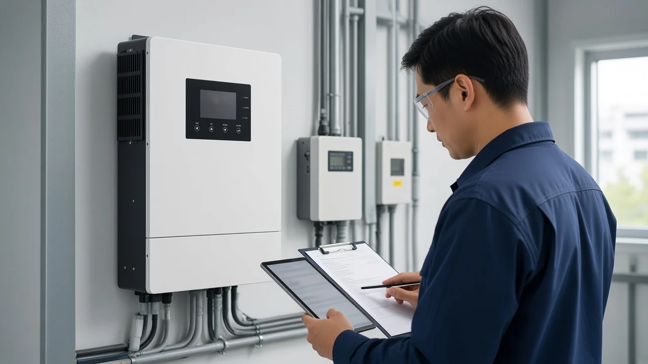
Two families share the phrase, and the clock separates them faster than any meter. An AC-side event clusters around the sunniest, busiest part of the day and clears when generation falls away. A DC-side event does the opposite: it shows up at first light on the coldest mornings of the year and has usually gone by the time anyone drives to site.
That single observation is worth making before any other check, because the two families send the case to different people. One ends with the network operator; the other ends with the array design.
| Signal | Grid over-voltage on the AC side | PV string over-voltage on the DC side |
|---|---|---|
| When it appears | Midday and afternoon, worst in summer and on high-generation days | First light, worst in winter, gone by mid-morning |
| Where it is measured | At the inverter AC terminals and again at the supply or metering point | Across the string at the tracker input, before the unit starts |
| What the unit is doing | Reducing output or disconnecting, which is the protective behaviour it is configured for | Blocking or refusing to start, which protects a hardware limit rather than the network |
| Usual cause | High supply voltage, plus the rise the site’s own export creates across its AC run | Series count set without margin for the coldest expected cell temperature |
| Who has to act | Network operator, or the installer who owns the AC run | The designer or installer who set the series count |
| What the remedy looks like | Cable and termination work, transformer or network action, or an agreed settings change | Fewer modules in series, or the same modules split across separate tracker inputs |
A third case sits between them and is worth knowing about: when a high AC voltage stops a unit exporting at full power, the DC bus can rise behind it and present as a bus fault. Repair-centre material flags this crossover explicitly, which is why the timing check comes before the meter.
The unit is usually reporting its supply accurately and doing exactly what its configuration requires. Grid over-voltage is the most common inverter complaint in mature solar markets, and the disconnect is a protective response to conditions on the network rather than evidence of a defect inside the box.
The envelope itself comes from regulation, not from the manufacturer’s preference. In Great Britain the statutory declaration for a low voltage supply is 230 volts between the phase and neutral conductors at the supply terminals, with permitted variation of not more than 10 per cent above or 6 per cent below, and the distributor carries a duty to keep supplies inside that declaration. Other markets declare their own values, which is why the same hardware behaves differently on two sites.
How an inverter must respond to an out-of-range supply is set by an interconnection standard rather than by the product. The IEEE standard covering distributed energy resources includes response to abnormal conditions within its scope, defines abnormal operating performance categories, and has since been amended to widen the allowable ranges of trip clearing time settings for one of those categories. The practical consequence for a channel desk is that “which grid code is this unit commissioned to” is a real question with a checkable answer.
There is also a signature worth recognising in the monitoring history. Line loss raises terminal voltage as the unit exports, the unit stops, the voltage falls back, the unit restarts, and the cycle repeats — which a portal renders as a cluster of identical faults every sunny day rather than one dramatic failure.
Two readings under comparable conditions settle the ownership argument; one reading settles nothing. Take the first at the inverter AC terminals and the second at the supply or metering point — the point of common coupling, in network language — in the same window and under the same export conditions, and the gap between them is the site’s own contribution.
Commercial diagnosis procedures put a baseline step alongside that pair: measure with the plant disabled, where the site permits it, so the background supply level is known before export is added. The voltage rise across the site’s AC run is then arithmetic rather than opinion.
| What the two readings show | Most likely reading of it | Where the case goes next |
|---|---|---|
| Both high, including with the array disabled or overnight | Network-side supply level, which the site’s export cannot explain | Network operator, with dated logs |
| Low at the supply point, high at the inverter terminals during export | Voltage rise across the site’s own AC run, or a termination problem | Installer: conductor size, run length, terminations |
| Inverter display disagrees with a calibrated meter on one phase | A measurement problem inside the unit or at its sensing point | Supplier, with paired photographs of both readings |
| Voltage normal but a neutral-to-earth code is also present | A neutral or earthing problem that can mimic a mains-voltage code | Installer, before the network operator is contacted |
One manual summary makes the last row concrete: a loose neutral termination can raise exactly the same mains-voltage code as an overloaded network, so the AC terminations, the neutral and the earth connection are inspected and tightened before anyone writes to the distributor.
From the field: an owner posted a controlled test on a UK solar forum — 246 V at zero export, 254 V while exporting 8.8 kW, and 245 V again the moment export was switched off — and that single before-and-after pair is what moved the network operator from blaming the installation to fitting its own logger for a week.
Because open-circuit voltage is the array parameter that rises as cells get colder, and the coldest cells of the year meet the first usable light of the day at the same moment. Below standard test temperature both the maximum-power-point voltage and the open-circuit voltage increase; above it, both fall.
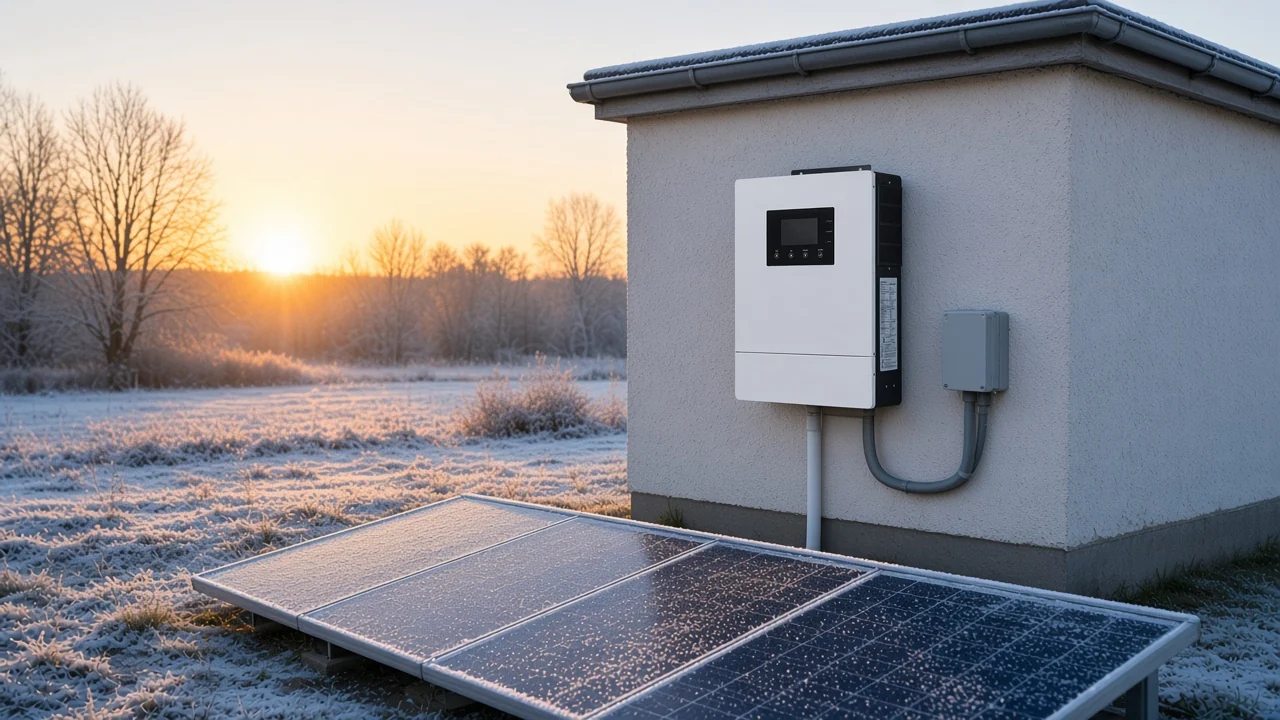
The physics is settled and the magnitude is small per degree, which is precisely why it gets missed. A cell-level photovoltaics reference puts the modelled fall in silicon open-circuit voltage at roughly 2.2 mV per degree Celsius while short-circuit current moves only about 0.06 per cent per degree, so voltage carries almost all of the temperature effect. For a real calculation the governing figure is the temperature coefficient printed on the module datasheet, applied to the lowest cell temperature the site will actually see.
A dawn-only fault that clears by mid-morning therefore points at the string design rather than at a failed component. One manufacturer’s winter operations note is unambiguous about the response to a DC over-voltage alarm: open the inverter’s DC switch immediately and reduce the number of modules in the string, rather than waiting to see whether it settles.
Treat repeated blocking as a countdown. Practitioners describe a charge controller refusing to run above roughly 140 V against a published 150 V input rating on two consecutive freezing mornings, and the replies in that thread are blunt that a single genuine over-voltage event can end the unit permanently.
Two different limits apply to the same string, and only one of them puts hardware at risk. The MPPT voltage range is a working window: above its ceiling the unit stops tracking well and production suffers. The maximum DC input voltage is a survival rating for the input stage, and passing it can destroy components that protection was never designed to save.
String length is the variable that moves both at once, which is why the acceptance check is run at two temperature extremes rather than one. University course material on stringing sets out the four conditions a string has to satisfy against a given inverter.
| Condition to check | Temperature case | Limit it is checked against | What failing it costs |
|---|---|---|---|
| String open-circuit voltage | Lowest recorded site temperature | Absolute maximum DC input voltage | Risk to the input stage |
| String maximum-power-point voltage | Lowest recorded site temperature | Upper end of the tracker window | Lost production while clipped or blocked |
| String maximum-power-point voltage | Average highest site temperature | Lower end of the tracker window | Poor or unstable tracking |
| String open-circuit voltage | Average highest site temperature | Start-up voltage requirement | Late or failed start on hot days |
The same course works those four checks against one example inverter rated for a 600 V absolute maximum, a 480 V tracker ceiling, a 250 V tracker floor and a 300 V start-up requirement, and those figures describe that example only. Every project needs the numbers from its own unit’s manual and its own module datasheet.
Where a unit has more than one tracker input, the remedy is often reconfiguration rather than removal. A community thread that started with a fault on a single string of 18 modules — cured by removing six — went on to establish that the stated maximum input applies per tracker input rather than to the sum, so two shorter strings on separate inputs can bring the same array back inside the rating.
Capture first, adjust second, because a settings change made to silence an alarm destroys the record that would have proved who owned the fault. Independent guidance on export limitation is explicit that protection or export settings must not be altered as a diagnostic test, and that a set-point change needs the agreement of the network operator or the facility owner.
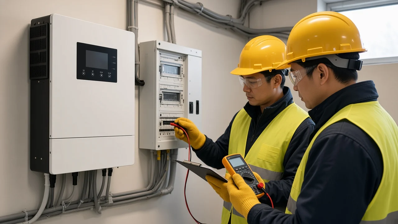
Most of the evidence already exists. A grid-connected inverter measures and stores the supply voltage at its own terminals continuously, so the event log and the voltage history can be exported before anyone visits — and breaches recorded overnight, when the array is generating nothing, cannot be attributed to the site’s own export.
On the DC side, the isolation work belongs to a qualified installer following the unit’s own manual. One published error-code manual sets out the sequence as switching the inverter off, allowing the input capacitors to discharge, opening the AC breaker, disconnecting the DC inputs, and then reconnecting one string at a time until the faulty string reappears, with a clear instruction that a string showing a grounding fault is repaired before it is reconnected at all.
Important: a logged over-voltage event can stay in the unit’s own history and can weigh on a later warranty discussion — so the configuration, the firmware version and the measured values are written down before anybody opens the settings menu.
A named set of records, rather than a description of the symptom, is what stops an escalation bouncing back. Support desks ask for the same things repeatedly, and assembling them once is faster than answering three rounds of questions.
| Record to send | Why the supplier needs it | Where it comes from |
|---|---|---|
| Exact fault code, with timestamps and the values shown at the event | Separates the AC family from the DC family without debate | Inverter event log export |
| Voltage history across at least one clear week, including overnight | Distinguishes a network condition from a site condition | Monitoring portal export |
| Paired readings: calibrated meter against the unit’s own display, per phase | Tests whether the unit is measuring correctly before anything is replaced | Site visit by a qualified person |
| Commissioned grid code, protection settings and firmware version | Shows which behaviour was actually installed on the unit | Commissioning record and unit menu |
| Array configuration: module type, series count, strings per input | Lets the supplier repeat the cold-temperature check independently | Design pack and module datasheet |
| Photographs: nameplate, wiring compartment, installation, active alarm on screen | Confirms identity, installation quality and the live condition | Site visit by a qualified person |
| Site conditions: lowest expected temperature, cable lengths and sizes on the AC run | Supports both the string check and the voltage-rise calculation | Design pack and as-built records |
Send that set and the supplier can reproduce the reasoning. Send a photograph of an alarm screen alone and the first reply will ask for the list above.
A project that records its voltage envelope before commissioning avoids most of what the sections above exist to unpick. The MOES WiFi Smart Hybrid Solar Inverter 4.2KW 6.2KW Off-Grid 48V fits that brief, because its page publishes both of the windows the triage turns on and it carries the monitoring feature that produces the fault alerts and remote records an escalation pack needs. The listing also states pure sine wave output, multi-protection, operation without a battery, and an LCD display whose acceptable input voltage and charging behaviour are configurable.
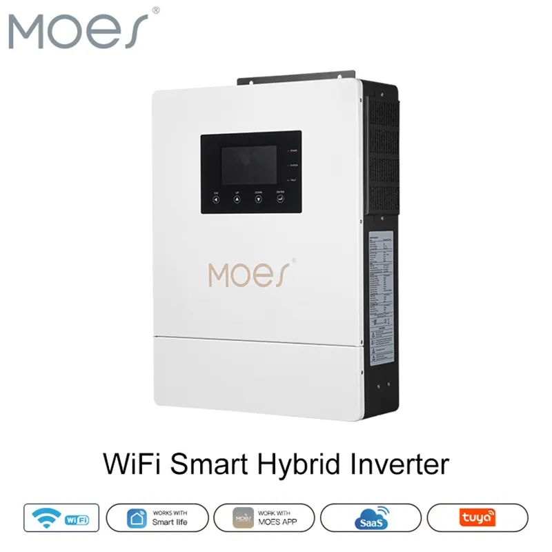
Read the page as an envelope rather than a performance promise. The live listing states a built-in MPPT solar controller of 80A/100A, an MPPT voltage range of 60V-450V, a 48V DC operating voltage, a single-phase AC operating voltage of 176-253V, 50Hz/60Hz operation and a 4.2KW/6.2KW power range. Those are the operating ranges the page publishes, and they are what a design pack should be checked against.
| Page-stated parameter | Value on the live listing | How it is used in this check |
|---|---|---|
| Built-in MPPT solar controller | 80A/100A | Sets the tracking-controller rating recorded in the design pack |
| MPPT voltage range | 60V-450V | The working window a cold-temperature string check is run against |
| DC operating voltage | 48V | The battery-side system voltage for the off-grid brief |
| AC operating voltage | Single phase 176-253V | The AC window the unit is stated to operate across |
| Operating frequency | 50Hz/60Hz | Regional operating frequency the unit is stated to accept |
| Range of power | 4.2KW/6.2KW | The output class the brief is sized around |
| Output waveform | Pure sine wave | Stated output quality recorded alongside the envelope |
Two boundaries matter when quoting it. The page publishes operating ranges and no protection trip setting, clearing time or grid-code profile list, so a project that needs those as contractual inputs has to request them in writing. And the stated AC window is an operating range rather than a protection threshold, just as the tracker window is separate from an absolute maximum input rating.
The unit sits in the Hybrid Inverter sub-category, with the Off Grid Inverter route alongside it and the wider MOES solar inverter range above both. Readers working a related decision can compare evidence types in the solar inverter efficiency comparison, size the unit with the power inverter sizing checklist, settle architecture in the on-grid and off-grid comparison, or review protection features in the integrated protection notes. For the written parameters a tender needs, contact the MOES team.
Yes, and this is the difference that matters most between the two families. Above the tracker window a unit generally stops tracking and loses production, but above the absolute maximum input rating the input components themselves are at risk, and practitioners describe that failure as permanent rather than recoverable. Protection shutdown is a last line of defence and was never intended as the design margin.
Because open-circuit voltage rises as cells cool, and first light on a freezing morning is the moment when the cells are coldest and the array is already producing voltage. As the day warms the cells, the string voltage falls back inside the rating and the fault disappears. That daily pattern is the clearest single indication that the cause is series count rather than a failed component.
The paired measurement answers it. If the supply reads high at the metering or supply point with the array disabled, or overnight, the site’s export cannot be the explanation and the case belongs with the network operator. If the supply point is fine but the inverter terminals climb during export, the gap is the site’s own voltage rise and the case belongs with whoever owns the AC run.
Not as a diagnostic step, and not unilaterally. Trip settings sit inside a commissioned grid code profile, and published guidance treats any change as something requiring the agreement of the network operator or the facility owner. Changing a limit to silence an alarm also erases the evidence that would have identified the real cause.
The tracker window describes where the unit can work, and the maximum DC input voltage describes what the hardware can survive. A string above the tracker ceiling costs production; a string above the absolute maximum threatens the input stage. A design has to pass both, checked at the site’s temperature extremes rather than at standard test conditions.
It can, which is the practical reason to document before adjusting. Practitioners report that some units retain a record of an over-voltage event in their own history, and that such a record can shape the discussion when a claim is raised. Capturing the measured values and the configuration first protects both the installer and the distributor.
Often, where the unit genuinely has independent tracker inputs. The stated maximum input voltage normally applies to each input rather than to the sum, so two shorter series strings can sit comfortably inside a rating that one long string exceeded. The unit’s own manual governs, because input architecture varies between models.
The event log export with timestamps, the voltage history including overnight periods, paired meter and display readings per phase, the commissioned grid code, protection settings and firmware version, the array configuration with module type and series count, and photographs of the nameplate and the active alarm. That set lets the supplier reach the same conclusion independently, which is what converts a report into an actionable case.


OTHER SMART DEVICES
Jun 13,2026
OTHER SMART DEVICES
Jun 12,2026
TUYA SMART HOME PRODUCTS
Jun 12,2026
 +86 137 3639 3028