

by NOVA

Oct 31, 2026
The MPPT vs PWM charge controller decision comes down to how the PV array, battery, and operating conditions fit together. MPPT controls the array’s operating point through a power-conversion stage; a conventional PWM controller switches the array-to-battery charging connection and generally operates the array near battery voltage while connected. MPPT is usually the stronger starting point when array voltage and battery voltage differ substantially or energy capture matters enough to justify extra cost. PWM can remain suitable for a small, properly voltage-matched system with modest charging needs. Neither label replaces checking the exact model’s limits and battery charging settings.
This guide compares controller technologies for battery-based solar systems. For a capacity calculation after choosing a technology, use the separate solar charge controller sizing guide. For the difference between charging batteries and producing AC power, see the inverter and charge controller comparison.
A conventional PWM solar regulator controls battery charging by switching the connection from the array. When connected, the battery strongly influences the array operating voltage. The controller can reduce charging as the battery reaches its required setpoints, but it does not provide the same array-voltage-to-battery-voltage conversion function as a typical MPPT charger.
This makes array and battery matching central to a PWM design. A module described as nominally suitable for a particular battery voltage still needs sufficient working voltage under the expected conditions. A name such as “12 V panel” is a system-description shortcut, not a statement that the module produces exactly 12 V throughout the day.
A larger array voltage is not a free upgrade for PWM. The design must stay within the controller’s permitted PV voltage and other ratings, and unnecessary voltage mismatch can leave available module power unused. Do not connect extra modules in series simply because the resulting voltage remains below an advertised absolute maximum.
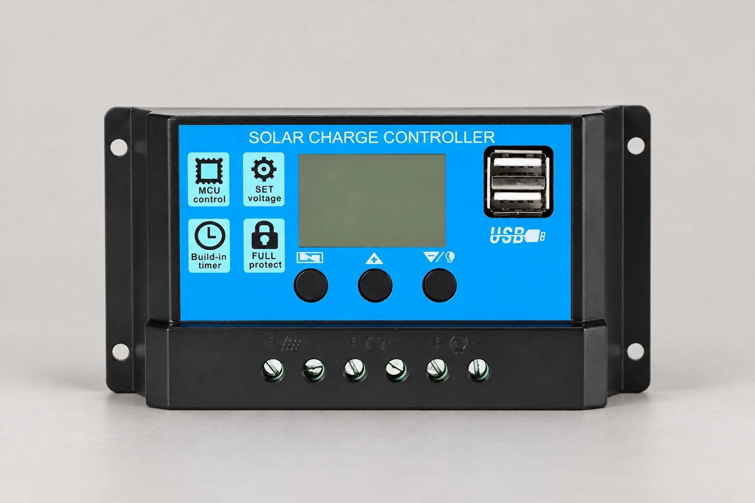
A PV module has an operating point at which voltage multiplied by current gives its maximum available power for the conditions. An MPPT controller adjusts the electrical operating point toward that region while its conversion stage supplies the battery at the required charging voltage. The array and battery can therefore operate at different voltages, within the controller’s specified operating range.
TU Delft’s maximum power point tracking lecture explains why the operating point matters and how power electronics influence it. This is the underlying reason MPPT can recover energy that a voltage-mismatched PWM arrangement would leave unused. The lecture is a technical explanation, not a performance test of any MOES controller.
MPPT is a control function, whereas PWM is also a general switching technique used inside many electronic converters. Consequently, finding pulse-width-modulated switching inside an MPPT circuit does not mean the product is a conventional PWM solar charger. Compare the complete charging architecture and documented behavior rather than treating those engineering terms as mutually exclusive at every circuit level.
The following table compares typical battery-charging architectures. Product-specific exceptions, ratings, and instructions take precedence; it is not a universal specification sheet.
| Decision point | Conventional PWM | Typical MPPT |
|---|---|---|
| Array operating point | Closely influenced by battery voltage while connected | Controlled toward the array’s available maximum-power region |
| Voltage matching | Array configuration must suit the battery-based charging arrangement | May accept higher array voltage and convert it to battery charging voltage within specified limits |
| Array-current interpretation | Array current is central to controller selection | PV input current and battery output current require separate checks |
| Upfront cost | Often attractive for simple, small charging duties | Additional conversion and control can increase purchase cost |
| Energy benefit | Depends strongly on module-to-battery voltage matching | Depends on conditions, array characteristics, and the battery’s ability to accept charge |
| Expansion | Extra modules must remain within the permitted system arrangement | More stringing options may exist, but voltage, current, and power limits still apply |
| Battery protection | Requires a suitable charging profile and supported settings | Requires a suitable charging profile and supported settings |
The practical comparison is between two complete proposals serving the same battery and loads. A cheap PWM unit compared with an oversized MPPT unit is not an informative technology test.
Start with MPPT when the array’s preferred operating voltage is appreciably above battery charging voltage, when a longer cable route makes a higher-voltage array worth evaluating, or when energy demand leaves little room for avoidable harvesting losses. Check the specific model before concluding that its voltage-conversion range supports your proposed arrangement.
A higher-voltage PV cable route may reduce current for the same power, but that is a system-design opportunity, not automatic permission to use thinner conductors. The designer still needs to check current ratings, voltage drop, insulation, protection, routing, and applicable installation rules. The battery-side cable can carry substantially different current from the array-side cable.
Cold conditions can increase PV voltage, which may improve the opportunity for MPPT conversion in a compatible system while also raising the risk of exceeding the controller’s voltage limit. PVEducation’s explanation of temperature effects describes the voltage relationship. Use the actual module coefficients and project design conditions rather than a generic “cold weather boost” percentage.
Partial shading needs its own assessment. It can reduce the power available and complicate the power-voltage curve. An MPPT label does not promise that shading losses disappear or that every tracking algorithm behaves identically. Improve module placement and electrical grouping before expecting the controller to recover energy that never reaches the array.
PWM can be reasonable for a small array deliberately matched to the battery, a maintenance-charging duty, or a simple project where the additional useful energy from MPPT has little operational value. The battery must still receive the appropriate charging profile, and the array must remain inside the controller’s limits across expected conditions.
For example, a lightly used remote instrument may have a generous charging surplus during its design season. The relevant question is whether the proposed PWM system can meet its energy requirement and battery needs reliably. Buying a more advanced controller does not by itself solve an undersized battery, seasonal shading, or a load budget that was never measured.
Likewise, an existing functioning PWM installation does not automatically need replacement. Check its energy shortfall, module configuration, battery condition, and wiring before recommending a change. An upgrade should address a documented limitation rather than follow a general claim that one technology always pays for itself.
Tracking efficiency, conversion efficiency, and additional daily energy describe different things. Tracking efficiency concerns how closely control follows the available maximum-power point. Conversion efficiency concerns power entering and leaving the conversion stage under stated conditions. Daily battery energy also depends on weather, operating limits, charging stage, losses, and battery acceptance.
A controller can track an array effectively while the battery has little need for more charge. Conversely, a battery with a real daily deficit may benefit from additional captured energy. Ask for the conditions behind any percentage: array and battery voltages, irradiance, temperature, charge state, measurement locations, and the comparison baseline.
A useful comparison test records PV input voltage and current alongside battery-side voltage and current, using the same defined conditions. IEA PVPS Recommended Practices for Charge Controllers discusses controller ratings and operating losses. It is a historical technical reference, so use current product instructions for model approval. For procurement, agree a documented acceptance method; a brief phone-app screenshot is not a controlled energy comparison.
Confirm battery chemistry, nominal bank voltage, permitted charging current, required voltage stages, temperature limits, and any communication requirements. A general “lithium supported” statement should lead to a review of the exact battery’s requirements and the controller settings available. Do not assume a lead-acid profile, temperature compensation rule, or equalization function is suitable for a lithium battery.
If multiple chargers serve one battery, review their combined possible charging current and how they coordinate. Include inverter/chargers and generator-fed chargers in that assessment. A controller selected only against PV wattage can still be wrong for a battery that cannot accept the proposed charging current.
Separate monitoring from charge control. Bluetooth, an LCD, or an app can make inspection easier, but it does not change an unsupported battery profile into a supported one. Establish which readings are available, how settings are protected, and what the unit does when communications are absent.
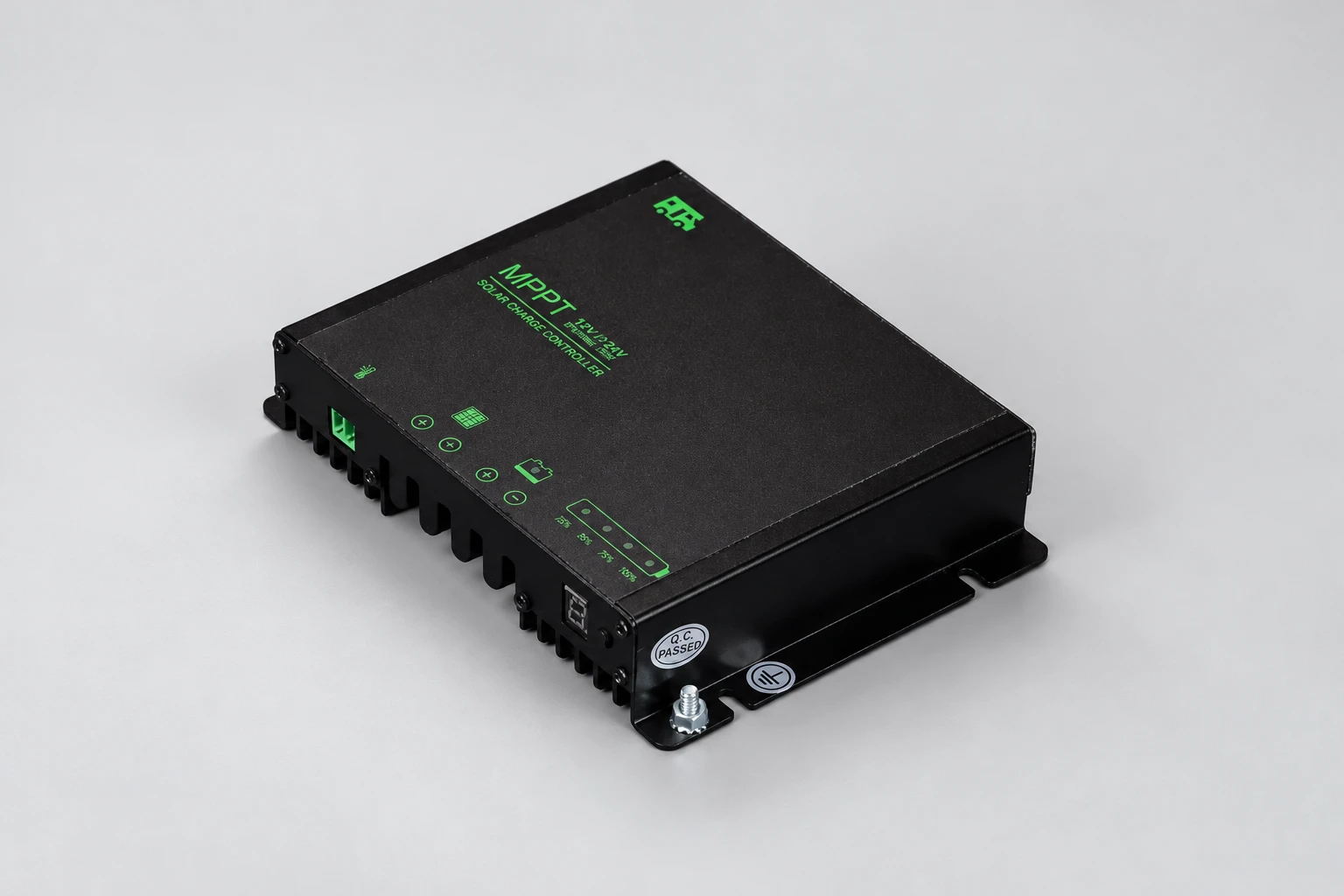
Use the solar charge controller range to begin the inquiry. MOES lists the NVJSS PWM controller family and several MPPT controller options. Family names and photographs help identify candidates; confirm the exact offered model and current documentation before approving the system.
Send the supplier your module datasheet, planned series/parallel arrangement, battery datasheet, site temperature range, expected daily load, installation location, and expansion plan. Request the exact PV voltage limits, input-current limits, output-current rating, battery-voltage-dependent PV power limits, charging settings, and installation instructions.
Keep this comparison separate from single-product approval. The existing PWM controller procurement guide addresses that narrower ordering task. Once the architecture is chosen, complete the numerical checks in the controller sizing guide and document the final configuration.
TU Delft’s lecture explains maximum power point tracking at the PV-system level. It helps explain the distinction in this comparison; it is not a wiring tutorial or an endorsement of a particular controller.
Watch the TU Delft maximum power point tracking lecture.
MPPT usually offers more operating flexibility and energy-harvesting opportunity, but the useful benefit depends on the array, battery, conditions, charging demand, and cost. A properly designed small PWM system can still be suitable.
Only within the exact controller’s permitted arrangement and limits. A physically accepted input voltage does not establish efficient array-to-battery matching or approve a particular string configuration.
No. Check the exact battery’s charging requirements against the controller’s supported settings, current limits, temperature behavior, and any required communications.
No. Tracking cannot replace sunlight blocked from modules, and performance under complex shading depends on the array and tracking implementation.
Check battery voltage, battery-side charging current, cold-weather PV voltage, PV input current, permitted PV power, and the required charging profile. No single amp or watt figure completes the selection.


OTHER SMART DEVICES
Jun 13,2026
OTHER SMART DEVICES
Jun 12,2026
TUYA SMART HOME PRODUCTS
Jun 12,2026
 +86 137 3639 3028