

by NOVA

Aug 31, 2026
A battery power inverter wiring diagram that survives permit review and commissioning starts with documented project inputs—not a forum thumbnail pasted into CAD. This page lists what installers, EPC coordinators, and distributors should freeze before anyone draws DC runs, sizes fuses, or submits a plan set. It is a solar inverter installation pre-check for diagram work, not a step-by-step wire-landing tutorial and not a buyer RFQ wording sheet.
When the input sheet passes, browse the solar inverter pillar for hardware families that match the logged topology.
Permits and commissioning fail when inputs are missing—not when the lines on the page look polished.
County reviewers and AHJ inspectors commonly ask for a coherent schematic before they debate wire color. Community installers report permit delays when the inverter terminal diagram never arrived from the manufacturer, or when the battery cable listing was left blank “to be decided in the field.” Those gaps show up as redraws, not as artistic flaws.
A battery-to-inverter diagram is a project record. It should inherit values from a signed input sheet: operating mode, bank voltage class, protection devices, grounding intent, and which drawing revision is archived. Skipping that sheet turns the diagram into a guess that warehouse picks and inspectors must unwind.
Write the operating mode / topology on the sheet before any conductor symbol hits the page.
Hybrid backup, off-grid stand-alone, and solar-plus-storage layouts add different branches to the same keyword. A hybrid inverter wiring diagram usually must show PV input, battery DC, and AC output paths together.
An off grid solar inverter wiring diagram may emphasize battery and load interfaces with different utility interconnection assumptions. Mark which story this job uses, then list every energy source and load segment the drawing must include.
| Topology row | Document on the input sheet | Diagram branch it controls |
|---|---|---|
| Operating mode | Off-grid / hybrid backup / grid-interactive intent | Which sources appear on the one-line |
| Inverter class | Hybrid charger/inverter vs stand-alone inverter | PV MPPT branch yes/no |
| Battery role | Required / optional / future-ready | Battery DC run shown or dashed |
| AC interface | Panel/subpanel connection type | AC output symbol set |
| PV array (if any) | String voltage class and MPPT / PV input window | PV input to inverter/charger |
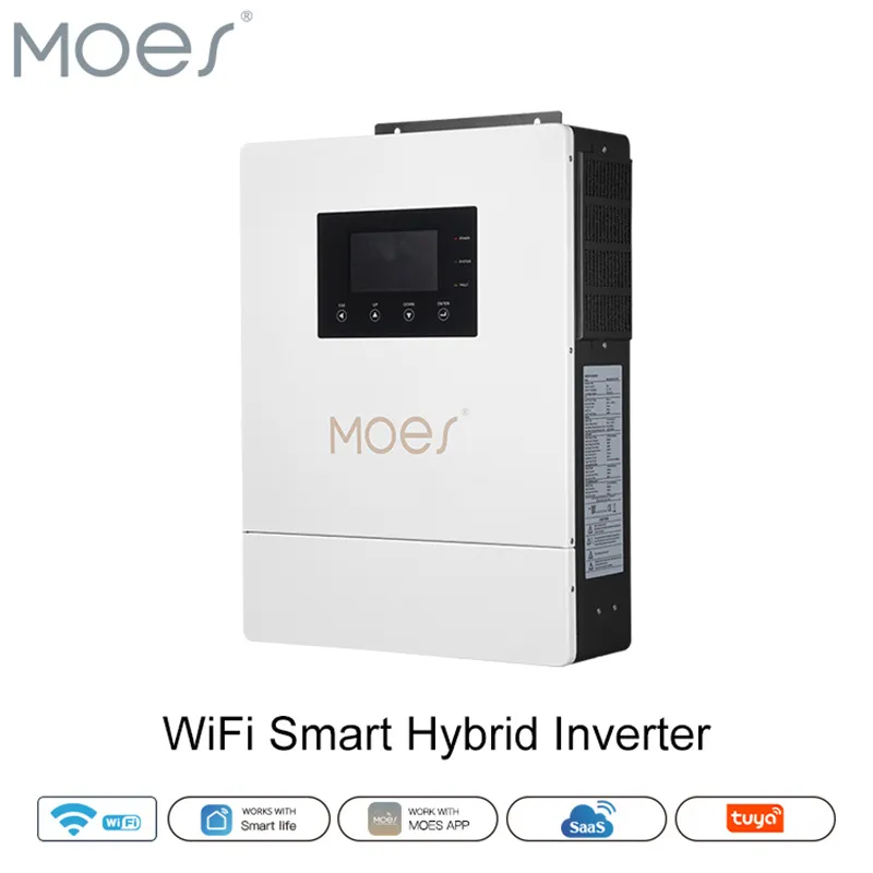
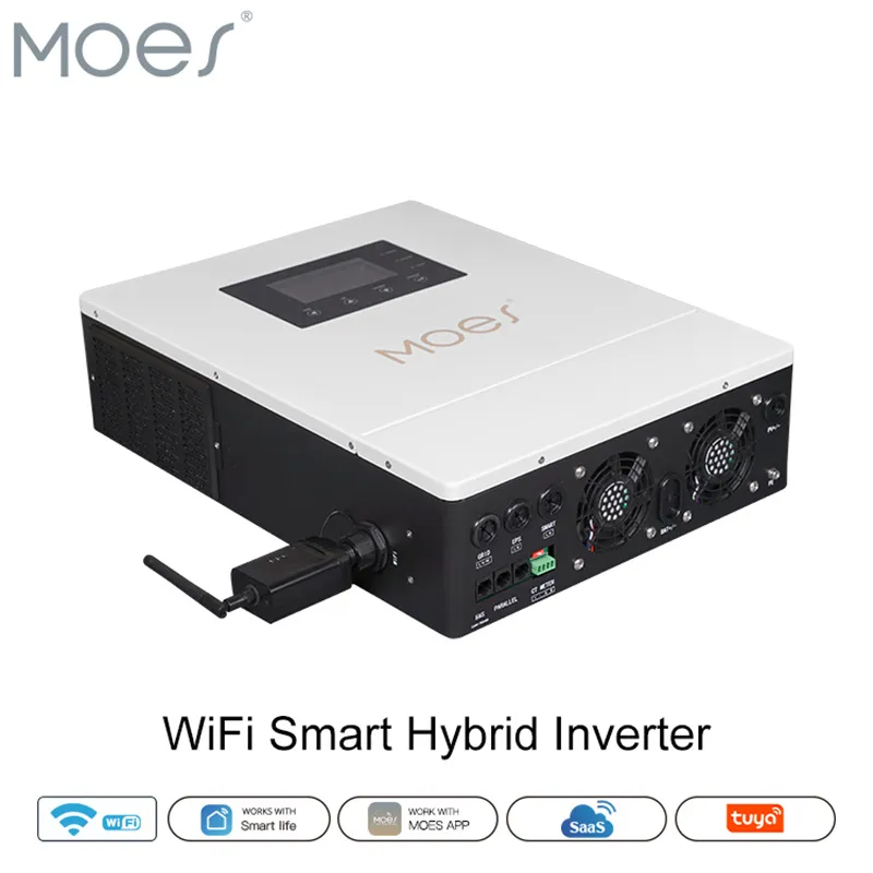
Some hybrid hardware can run without a battery for certain commissioning steps—the MOES WiFi Smart Hybrid listing notes battery-optional operation on its product page. Even then, the diagram should still show where the bank would land so field changes do not orphan PV or AC branches.
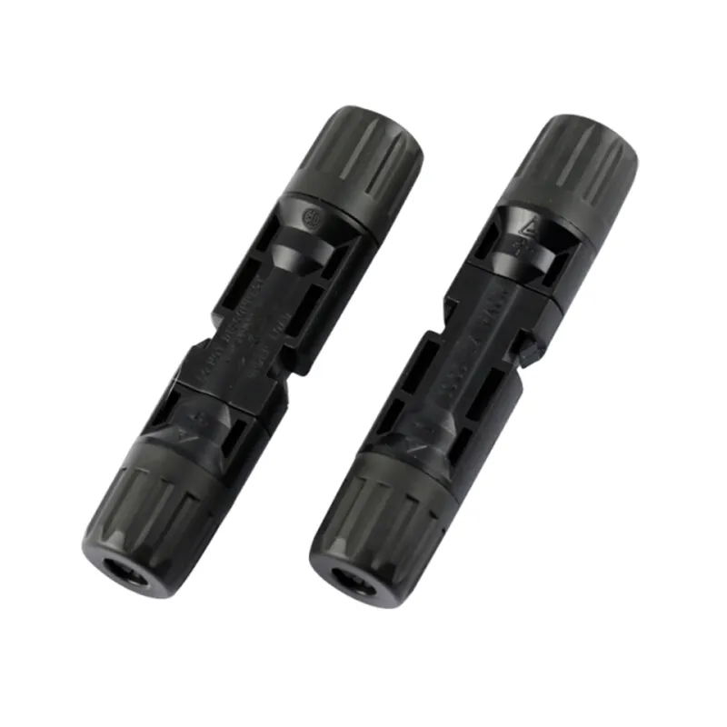
Log nominal voltage class, chemistry family, module count, and series/parallel layout before cable or fuse symbols are placed.
Educational summaries of residential lithium energy storage often describe nominal DC classes around 48 V for many home-scale banks. Your sheet should carry the exact nameplate or design voltage the installer expects—not a rounded guess from a marketing slide. Chemistry and BMS limits matter because parallel strings raise balance and conductor-sharing questions that appear on multi-battery diagrams.
Three parallel packs without busbar notes are a common source of field imbalance. Capture whether the design uses a busbar, fused per-string taps, or a single home-run pair so the diagram matches the intended maintenance path.
Document DC conductor / cable run listing intent, overcurrent protection (OCPD) / fuse type, and DC disconnect location before the battery-to-inverter span is drawn on the diagram.
Forum permit threads repeat the same blockers: which flexible DC cable listing the AHJ accepts, how close the fuse sits to the battery positive, and whether an isolation switch lands before or after the protector. The input sheet should answer those rows explicitly so the diagram is not the first place those decisions appear.
| DC protection field | What to write | Why inspectors care |
|---|---|---|
| Conductor class / listing note | Manufacturer-approved or AHJ-accepted DC cable family | Permit folders often reject “TBD cable” |
| Fuse or breaker type | Class-T, MRBF, ANL, or listed DC breaker model class | Must match available fault current |
| Fuse location | Battery-side positive, before or after disconnect as designed | Short-circuit protection path |
| Disconnect ID | Listed DC disconnect model or spec sheet reference | Lockout/tagout and labeling |
| Run routing class | Conduit, free air, or enclosure segment notes | Affects ampacity review |
Important: Permit applicants often stall when the schematic omits an accepted battery cable listing or inverter cable sizing reference—record both on the signed sheet before CAD export. (source: installer permit discussions)
Follow inverter and battery manufacturer cable guidance for the continuous current class you document. The diagram should cite that reference in the notes block rather than inventing a gauge from a generic table.
Obtain the manufacturer inverter/charger terminals diagram and equipment grounding / EGC notes before lugs are drawn on the page.
Hybrid and off-grid inverter/chargers publish different lug layouts, dual battery terminals, PV inputs, and AC passthrough configurations. When a county asks for an inverter wiring diagram—as happens with high-power off-grid units—teams cannot finish the sheet without that terminal drawing in the project folder.
Grounding is not a footnote. Inspection checklists for energy storage installations commonly include equipment grounding conductor sizing and disconnect grounding terminals alongside OCPD verification. Your input sheet should list which grounding conductors the diagram will show between battery enclosure, inverter chassis, and AC equipment grounding system.
Record code edition notes, disconnect labeling, and permit / labeling archive drawing-set IDs so the permit package matches what crews install.
Field inspection references for energy storage programs expect directories at disconnect means, proper OCPD and disconnect wiring, and maintenance information that includes wiring diagrams, control drawings, and programming instructions. Treat those items as archive rows, not as post-install paperwork.
| Archive field | What “done” looks like |
|---|---|
| Code edition note | NEC/adopted edition the team cites for this address |
| Drawing set ID | Sheet number, revision, date, author |
| Disconnect labels | Nominal DC voltage and available fault current language planned |
| As-built owner | Who updates the diagram after field changes |
| Manuals bundled | Inverter, battery, and disconnect cut sheets in the submittal |
Projects should note which electrical code edition applies through the AHJ without copying article numbers into marketing prose. The objective is a traceable documentation trail: inputs → diagram → labeled install → archived as-built.
Freeze the rows below on one signed page before CAD or permit upload starts.
| Input | What “done” looks like |
|---|---|
| Topology / mode | Off-grid, hybrid backup, or other—named on sheet |
| Inverter class + SKU family | Hybrid vs stand-alone; manufacturer series |
| Bank voltage class | Nameplate or design nominal DC voltage |
| Bank layout | Series/parallel count; busbar yes/no |
| BMS / continuous current limit | Published limit or datasheet reference |
| DC cable listing intent | Approved family or “pending AHJ” with owner |
| Fuse / OCPD type + location | Device class and battery-side placement |
| DC disconnect | Model/spec and mount location |
| Terminal diagram on file | Manufacturer drawing revision logged |
| PV input (if hybrid) | String voltage within published MPPT window |
| AC interface | Panel connection ID and grounding path |
| Labeling + archive | Disconnect labels; drawing ID; as-built owner |
| Sign-off | Lead installer + reviewer date |
Hand the same sheet to estimating, purchasing, and the permit coordinator. Any blank row means the battery power inverter wiring diagram is not ready to publish internally—let alone to an AHJ portal.
Choose the MOES WiFi Smart Hybrid Solar Inverter when the signed sheet already passes the topology, bank, and interface rows above.
Open the hybrid product listing for terminal specs after those gates clear.
Live product data for that listing includes 48 V DC operating voltage, AC 176–253 V single phase at 50/60 Hz, power range 4.2 kW / 6.2 kW, and MPPT voltage range 60–450 V with built-in MPPT controller. Quote those figures only when that exact SKU is on the sheet.
| Hybrid listing parameter | Documented value (product page) |
|---|---|
| DC operating voltage | 48 V |
| AC operating voltage | Single phase 176–253 V, 50/60 Hz |
| Power range | 4.2 kW / 6.2 kW |
| MPPT voltage range | 60–450 V |
The page also states the unit can operate without a battery—record whether the diagram shows a bank anyway for future expansion. When bank class, topology, or AC interface fails the sheet, browse other families on the hybrid inverter category or the generic dc-to-ac power inverter system inputs guide for buyer-wording RFQs. Distributors can request samples through Contact Us once the wiring input sheet is signed.
Freeze topology, bank voltage class, DC cable and protection rows, inverter terminal diagram availability, grounding path, AC interface, and permit archive fields on one signed sheet before CAD work begins.
Size depends on documented continuous current, approved cable listing, run length, and manufacturer guidance—not a single universal gauge. Log those inputs on the sheet; let the licensed designer or AHJ review convert them to a sized conductor on the diagram.
Place overcurrent protection on the battery-side positive path as close as practicable to the source, with disconnect location noted so the diagram matches service and inspection expectations for the jurisdiction.
Document a listed DC disconnect (or approved isolation means) with ID, location, and labeling plan. Inspection-oriented checklists for energy storage installations treat disconnect and grounding terminals as core review items.
Show PV input, battery DC, and AC output branches consistent with the operating mode row, plus protection and grounding symbols tied to the input sheet—not a battery-only sketch when the hardware is hybrid.
No. Record equipment grounding conductor paths and bonding points on the input sheet so the diagram includes them before submittal.
Stop internal release until the terminal diagram and manual revision are archived. Permit-driven projects commonly cannot finish schematics without that drawing.
When the signed sheet matches the hybrid parameter table above—bank class, hybrid/off-grid topology, and PV/AC interface rows that align with that SKU’s published limits.


OTHER SMART DEVICES
Jun 13,2026
OTHER SMART DEVICES
Jun 12,2026
TUYA SMART HOME PRODUCTS
Jun 12,2026
 +86 137 3639 3028