

by NOVA

Sep 02, 2026
A 3 phase solar inverter wiring diagram that survives permit review starts with documented project inputs—not a three-line pinboard sketch pasted into CAD. This page lists what installers, EPC coordinators, and distributors should freeze before anyone draws L1/L2/L3 runs, assumes a neutral, or submits a plan set. It is a solar inverter installation pre-check for diagram work, not a step-by-step wire-landing tutorial and not an ampacity table dump.
When the input sheet passes, open the solar inverter pillar to shortlist hardware families that match the logged three-phase topology. For battery-bank and DC-protection matrix rows, use the sibling battery power inverter wiring diagram project inputs checklist instead of restating that matrix here.
Permits and commissioning fail when inputs are missing—not when the lines on the page look polished.
Three-phase jobs amplify that risk. Community builders describe manufacturer three-phase diagrams that read like dense road maps, then discover expensive 3-pole breakers, combiner mains, and interconnection notes only after CAD is already in motion. Domestic planners likewise stall when nobody writes down whether the inverter is assumed to share power evenly across phases or to follow load—because that assumption changes how the house and garage circuits are drawn.
A three-phase solar inverter diagram is a project record. It should inherit values from a signed input sheet: phase topology, grid connection class, PV/MPPT notes, AC conductor set (including neutral and earth intent), protection devices, and which drawing revision is archived. Without that sheet, the drawing becomes a warehouse and inspection guess that crews rewrite on site.
Write the phase topology and grid connection class on the sheet before any conductor symbol hits the page. Solar inverter installation work for three-phase sites fails early when those rows stay verbal.
On-grid three-phase, hybrid three-phase with backup ports, and multi-inverter paralleling layouts add different branches to the same keyword. A three phase solar inverter wiring package for commercial sites usually starts here—before anyone argues ampacity.
Mark whether the service is treated as Wye-with-neutral or delta-without-neutral, because that choice controls whether a neutral appears on the AC side of the drawing. Also record the phase-balance / distribution assumption the designer is using—even-share versus load-following—so estimating and field wiring do not invent opposite stories.
| Topology row | Document on the input sheet | Diagram branch it controls |
|---|---|---|
| Operating mode | On-grid three-phase / hybrid three-phase / multi-inverter parallel | Which sources and ports appear on the one-line |
| Grid connection class | Supply-side vs load-side interconnection intent | Point-of-connection symbols and disconnect grouping |
| Neutral class | Wye-with-neutral vs delta-without-neutral | Whether N is drawn on AC terminals |
| Phase-balance assumption | Even share vs load-following / unknown-pending OEM | How load circuits are allocated across L1/L2/L3 |
| Inverter count | Single three-phase unit vs paralleled set | Parallel/comms and combiner branches |
Interconnection and permitting paperwork belongs in the same freeze as topology. Treating an on grid solar inverter connection diagram as “just drawings” while interconnection class stays verbal is how plan sets bounce.
Log string voltage class, polarity intent, and MPPT / PV string channel assignment before DC symbols are placed.
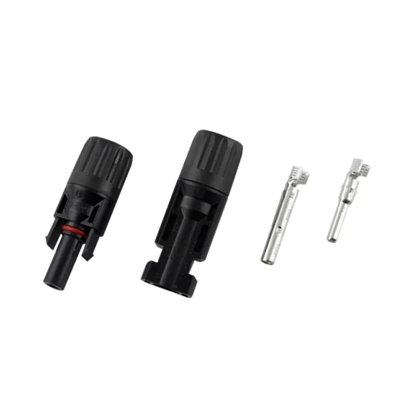
Three-phase on-grid install guides commonly ask teams to confirm inverter capacity against the array, review DC voltage/current limits, and map MPPT input configurations before cables land. Your sheet should carry the open-circuit voltage class the designer expects, how many strings feed which MPPT, and whether DC isolators sit at the array, the inverter, or both. Polarity checks and MC4-style connector family notes belong here so the diagram is not the first place those decisions appear.
Leave battery series/parallel bank math to the battery sibling checklist when a hybrid bank is in scope. This page only needs enough PV/MPPT rows for the three-phase inverter diagram to show the solar DC branch correctly.
Document AC output L1/L2/L3, neutral, and protective earth (PE) intent before phase legs are drawn.
Many three-phase string-inverter manuals describe a five-conductor AC connection pattern—L1, L2, L3, N, and PE—when the grid class requires a neutral. That pattern is a documentation prompt, not a universal law: delta-without-neutral services must not inherit an N conductor simply because a five-wire thumbnail looked complete. Write the intended conductor set, torque/owner notes if the OEM requires them, and whether additional chassis PE bonding is specified locally.
Also capture AC voltage class language the project cites (for example, how the selected OEM labels 3/N/PE systems) without inventing a site voltage that the utility letter never stated. The diagram should repeat the sheet—not replace a missing interconnection study.
| AC field | What to write | Why it blocks CAD |
|---|---|---|
| Conductor set | L1/L2/L3 + N yes/no + PE | Wrong N assumption forces redraws |
| Terminal diagram on file | Manufacturer AC terminal drawing revision | Lugs cannot be guessed from clipart |
| Earth / bonding | Chassis PE and additional bonding yes/no | Missing PE symbols fail inspection packages |
| Backup / EPS ports (if hybrid) | Which loads ride which ports | Hybrid diagrams need port IDs early |
| Metering intent | Per-phase CT yes/no | Uneven phase currents matter for export controls |
Freeze protection devices and phase sequence ownership before the drawing shows isolators and breakers.
Install education for three-phase on-grid inverters routinely lists AC isolators, RCD or equivalent residual devices where required, and appropriately rated fuses or breakers alongside a phase-sequence check before energizing. Community three-phase builds add another layer: which 3-pole breakers belong in combiners, which can be main-lug-only with upstream OCPD documented, and how supply-side versus load-side interconnection changes that story. Put device IDs, pole count, and location notes on the sheet so CAD is not inventing a $2,000 breaker farm.
Important: If a combiner or panel is main-lug-only, write the upstream overcurrent device location on the plan-set notes before submittal—inspectors reject surprises more often than they reject documented MLO designs.
Metering teams also remind installers that three-phase inverters can show uneven phase currents at low production or standby. When export limiting or revenue metering is in scope, record whether each phase gets its own CT so the diagram’s instrument transformers match the control narrative.
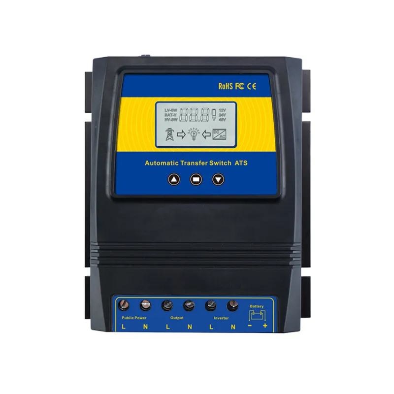
Record code-edition notes, disconnect labels, and drawing-set IDs so the permit / label archive can travel with the diagram.
Projects should note which electrical code edition applies through the AHJ without copying article numbers into marketing prose. Keep interconnection package IDs, manufacturer terminal diagrams, and as-built owners in the same folder as the wiring drawing. Field teams that treat labeling as a last-day sticker exercise usually rediscover missing disconnect directories during inspection.
| Archive field | What “done” looks like |
|---|---|
| Code edition note | Adopted edition named for the AHJ |
| Interconnection class on file | Supply-side / load-side intent matching the topology row |
| Disconnect labels | Phase ID, source, and available-fault-current language planned |
| Drawing set ID | One-line / wiring diagram revision logged |
| As-built owner | Who updates the diagram after field changes |
| Manuals bundled | Inverter AC/DC terminal cut sheets in the submittal |
Federal solar program language treats interconnection and permitting streamlining as core delivery work—not optional paperwork. Your archive should reflect that seriousness even when the CAD looks finished.
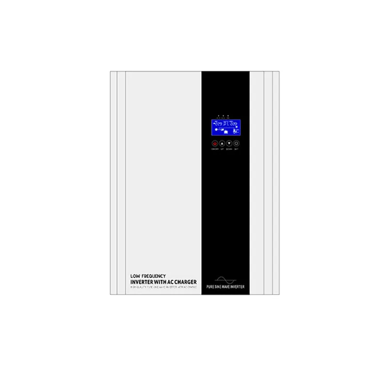
Freeze the rows below on one signed page before CAD or permit upload starts.
| Input | What “done” looks like |
|---|---|
| Phase topology / mode | On-grid three-phase, hybrid three-phase, or parallel set—named |
| Grid connection class | Supply-side vs load-side intent written |
| Neutral class | Wye-with-N vs delta-without-N |
| Phase-balance assumption | Even share / load-following / pending OEM |
| PV string + MPPT map | Voc class; strings per MPPT; DC isolator locations |
| AC conductor set | L1/L2/L3 + N yes/no + PE |
| Terminal diagram on file | Manufacturer drawing revision logged |
| Protection devices | AC/DC isolators; breaker/RCD intent; pole count |
| Phase-sequence owner | Who verifies rotation before energizing |
| Metering / CT intent | Per-phase CT yes/no when export controls apply |
| Labeling + archive | Disconnect labels; drawing ID; as-built owner |
| Sign-off | Lead installer + reviewer date |
Hand the same sheet to estimating, purchasing, and the permit coordinator. Any blank row means the 3 phase solar inverter wiring diagram is not ready to publish internally—let alone to an AHJ portal.
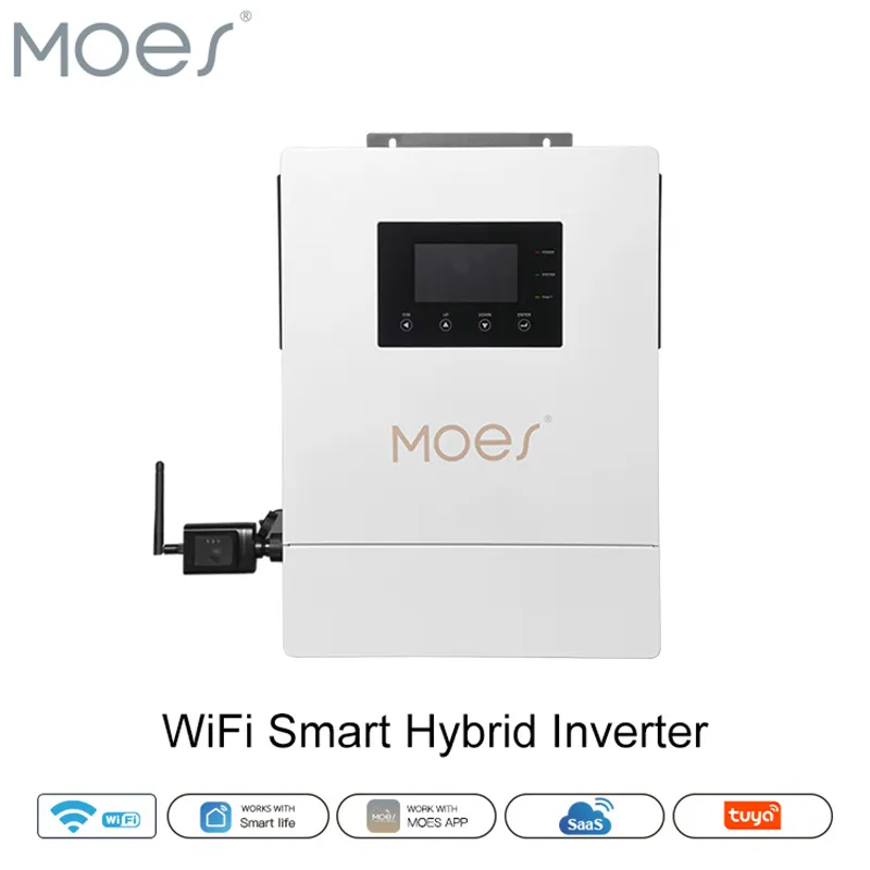
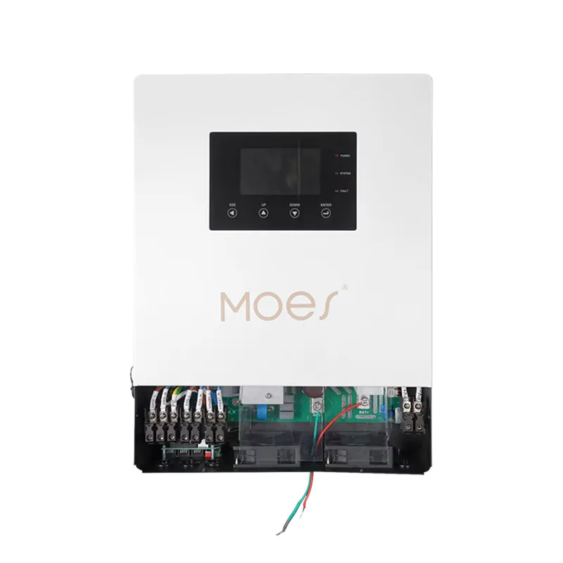
Choose the MOES WiFi Smart Hybrid Solar Inverter when the signed sheet already passes the topology, PV/MPPT, and AC-class rows above—and those AC-class rows match the listing’s published single-phase output.
Open the hybrid product listing for terminal specs after those gates clear.
Live product data for that listing includes 48 V DC operating voltage, AC 176–253 V single phase at 50/60 Hz, and power range 4.2 kW / 6.2 kW. Quote those figures only when that exact SKU is on the sheet. Do not treat this listing as three-phase AC nameplate hardware.
| Hybrid listing parameter | Documented value (product page) |
|---|---|
| DC operating voltage | 48 V |
| AC operating voltage | Single phase 176–253 V, 50/60 Hz |
| Power range | 4.2 kW / 6.2 kW |
When the signed sheet requires true three-phase L1/L2/L3 AC output, keep the same input checklist and shortlist other families on the solar inverter pillar or hybrid inverter category after the conductor-set rows are frozen. For battery-bank voltage class, fuse placement, and DC disconnect matrix work, open the battery power inverter wiring diagram project inputs sibling instead of copying those rows here. Distributors can request channel mapping through Contact Us once the wiring input sheet is signed.
Freeze phase topology, grid connection class, neutral presence, PV/MPPT notes, AC L1/L2/L3/N/PE conductor set, protection devices, phase-sequence ownership, and permit archive fields on one signed sheet before CAD work begins.
Many three-phase string inverters document a five-conductor AC set (L1, L2, L3, N, PE) when the grid class includes a neutral—but delta-without-neutral services omit N. Log the intended conductor set from the interconnection class and OEM terminal diagram; do not copy a five-wire thumbnail blindly.
Only when the documented grid topology is Wye-with-neutral (or another class that requires N). If the service is delta-without-neutral, drawing an N conductor creates a false diagram. Capture neutral class as its own input row.
Record string Voc class, strings-per-MPPT assignment, DC isolator locations, and polarity/connector ownership so the solar DC branch on the drawing matches the array design—not a blank “PV in” arrow.
List AC isolator, residual device (where required), and breaker/fuse intent with pole count and location before CAD. For three-phase combiners, also note whether each enclosure is main-breaker or main-lug-only with upstream OCPD identified on the plan set.
Not as a safe design assumption. Planners debate even-share versus load-following behavior because it changes how house circuits and EV loads are allocated. Write the project’s phase-balance assumption on the topology row and confirm it against the selected OEM before releasing the diagram.
Keep code-edition note, interconnection class, disconnect labels, drawing revision IDs, as-built owner, and OEM terminal cut sheets with the submitted diagram set.
When PV/MPPT and AC-class rows match the published single-phase parameters in the product table above for that SKU. If the sheet requires three-phase AC output nameplate capability, shortlist other hardware after the same input gates pass.


OTHER SMART DEVICES
Jun 13,2026
OTHER SMART DEVICES
Jun 12,2026
TUYA SMART HOME PRODUCTS
Jun 12,2026
 +86 137 3639 3028