

by NOVA

Oct 10, 2026
A power inverter works by reversing battery direct current so the load receives alternating current. how does a power inverter work names that path, from the DC source through the inversion stage to the AC side.
The noun for the device sits on what is a power inverter. The job description sits on what a power inverter does. A PV string path sits on how a solar inverter works.
Browse families on the solar inverter hub. Stay here when the source is a battery or another stored-DC bus and the question is the conversion path itself.
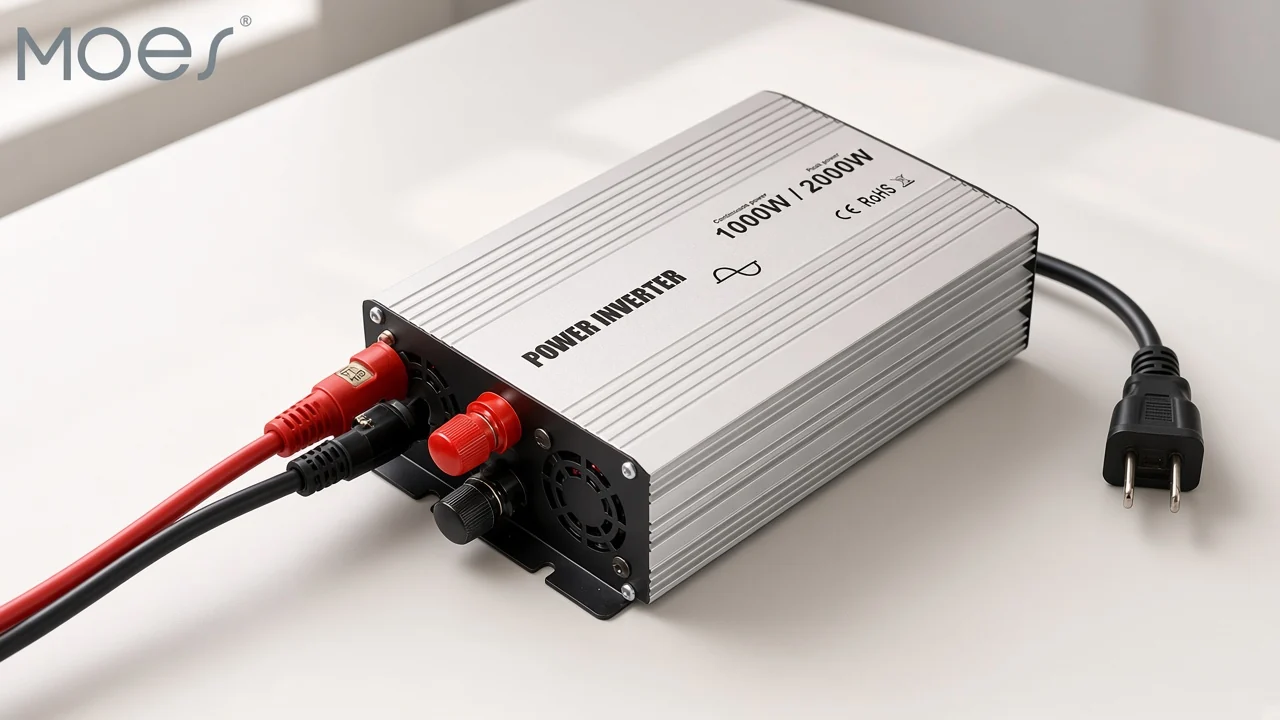
Battery or other stored direct current enters the conversion path, and the power inverter does not create that energy.
The inverter does not produce any power; the power is provided by the DC source. Alternating current shows up only after something reverses the flow.
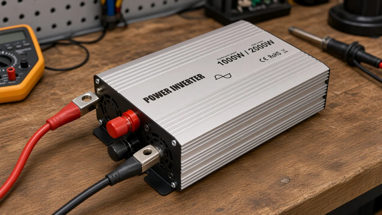
Picture a distributor bench with a battery bank on the left and a small AC tool on the right. The cable from the battery still carries direct current. Nothing about that cable alternates until it reaches the chassis.
A vehicle electrical system is the same kind of source when the listing’s own wording says so. Fuel cells and other stored-DC buses follow the same entry rule. The path starts at whatever holds one polarity, not at a panel string.
If the project drawing shows photovoltaic modules and an operating window, leave this page. That sequence begins where array voltage is held before the switches. Mixing the two stories makes the quote ask for the wrong input line.
Buyers sometimes treat the chassis as a generator because outlets appear on the front. The outlets are the end of the path. The watt-hours still leave the battery, and an empty bank means quiet outlets even when the switches are healthy.
The inversion stage reverses direction by alternating switch pairs, which is what an h-bridge is built to do.
A dc to ac converter is the circuit name for that stage. Direct current wants one direction. The switches disagree with it, on purpose, many times each second.
One diagonal pair connects the DC bus so current leaves toward the load in the first direction. The other pair connects the same bus the opposite way.
The load then sees current that has turned around. That turnaround is the whole trick at principle level.
Controllers keep the two switches on one leg from conducting together. Overlap would short the DC source.
A short pause between the pair, often called dead time, is the practical guard. The pause is a design detail, not a number this page assigns to a MOES listing.
Pulse width is the next control, still without a frequency figure. Narrow pulses pull the average voltage down.
Wide pulses push it up. Across one AC cycle the average can lean toward a sine even though each instant is only on or off.
From the field: A forum reader who had never opened a unit asked whether the box uses a transistor or capacitors (Physics Forums). The reply names an oscillator, switching transistors, and a transformer, and it notes that a square wave carries harmonics while extra electronics clean the shape.
Capacitors do show up, but they are not the part that flips polarity. They stiffen the DC bus and, with inductors, soften what the load feels. Asking only “transistor or capacitor” misses the oscillator that tells the switches when to move.
Low-voltage battery inverters often use MOSFETs for those switches. Higher-voltage stages often use IGBTs.
The buyer-facing path does not change: pairs still alternate, and the load still sees a reversal. The semiconductor family is a build choice inside that stage.
A transformer and filter parts finish the alternating current the load actually sees.
Two household designs are common. One raises the DC first, then chops that higher bus into AC.
The other makes AC at battery voltage and lets a line-frequency transformer raise it. Both still depend on the reversal that came before the coil.
A line-frequency transformer uses electromagnetic induction. Reversing current in the primary induces alternating current in the secondary. A coil by itself does not turn steady DC into AC, because a steady field does not keep inducing.
Inductors and capacitors let current rise and fall more gradually than a raw square-wave output. The load then feels a smoother rise instead of a hard corner on every flip. That smoothing is filtering, not a second energy source.
Utility practice lands on 50 Hz or 60 Hz. The listing’s own frequency cell is where a quote copies the pair that applies, rather than a guess from the country name in an email signature.
Heat leaves in the switches, the magnetics, and the filter. Output power stays below input power because some energy warms the chassis. That is conservation, and it is not a printed efficiency percent on the example page.
Fans and finned metal on a real chassis are there for that heat. A quiet bench sample can still be the wrong unit if the DC cable is thin and the voltage sags under load. The path explains the sag: the source, not the AC label, has to supply the current.
Waveform class is the printed name of the output shape, and it belongs on the quote as one field.
Simple reversal, held for half a cycle, draws a square wave. Changing how long each flat pulse lasts draws a modified shape with a step near zero.
Varying pulse width through the cycle draws something much closer to a sine. Those three results are different control choices on the same reversal idea.
Some loads only want energy. Heaters and simple lamps are often in that group.
Controls, audio gear, and many motor drives are pickier, and a rough edge can buzz, run warm, or refuse to start. The field to copy is the shape name the page prints, not a new matrix built in the email.
Community replies say a basic h-bridge “creates a square wave, rather than a sine wave,” and that extra circuitry is what smooths it. That is an expectation, not a lab report on any MOES unit.
If the listing says pure sine wave, copy that phrase. If another listing says modified sine wave, copy that phrase instead.
The taxonomy of types, and the head-to-head waveform comparison, already have their own pages. This path only needs the class so the quote does not treat every chassis as the same shape.
The path puts input voltage, the printed power line, and waveform class on the quote.
Input voltage is the DC operating voltage the battery must match. A 12-volt bank on a chassis built for a higher DC bus is a different project, even when the AC outlet label looks familiar.
Copy the cell. Do not translate it from a vehicle story.
The printed power line is next, and it is easy to blur. A title can carry two watt strings while a parameter table carries a range.
Peak wording on a product photo is a third place the same idea can appear. Each string stays where it was printed.
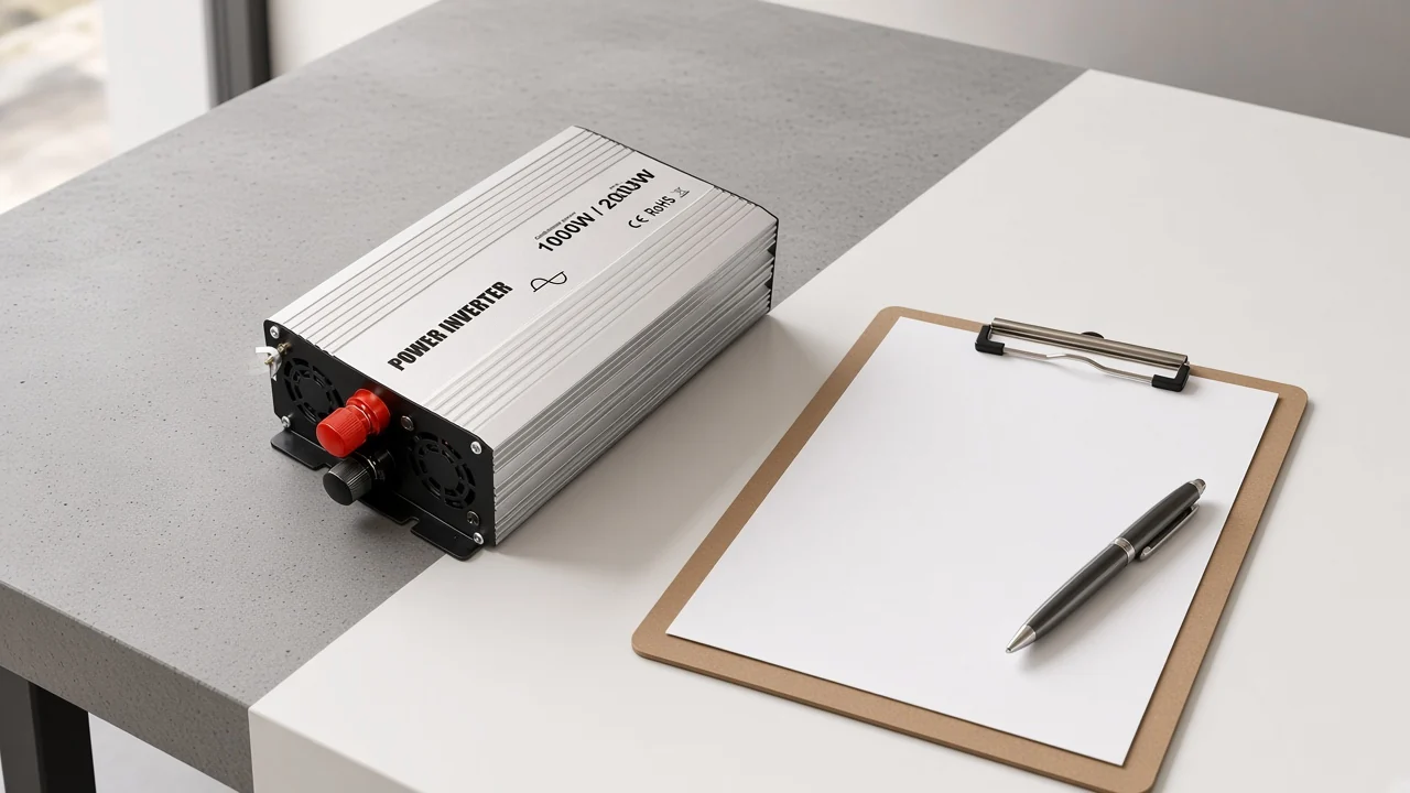
The listing table prints DC operating voltage 12V/24V/48Vdc, output voltage 110V/120V/220V/240Vac, and operating frequency 50Hz/60Hz. The same table prints a power range of 300W ~ 6000W. The product photo on that listing prints Continuous power 1000W / Peak power 2000W.
Those three power writings are not interchangeable labels. The table’s range cell does not say continuous, and it does not say peak.
The photo does use those two words, for the strings on the chassis. A quote should repeat the photo words only beside the photo, and repeat the table range only beside the table.
No multiplier is printed between those strings. Do not invent one.
If a later datasheet row names surge, ask for that row. Until it exists, peak on the photo and the range in the table are the power evidence this listing gives.
Waveform class is the third field. On this example the page description says pure sine wave, and the series line says high-frequency pure sine wave.
“High-frequency” here is the page’s class word. It is not a switching-frequency number, and none is printed.
Output voltage and output frequency travel with the AC side of the same table. They are part of copying the path, beside the three fields above.
Protection names on the page — over current, over voltage, over temperature, overload, short circuit, low voltage — are labels. They are not a test report.
| Path stage | What the buyer writes down |
|---|---|
| Battery or stored DC in | DC operating voltage as printed |
| Inversion stage | Waveform class as printed |
| AC at the load | Output voltage and operating frequency as printed |
| Power the path can hand off | Table power range, plus continuous and peak only where the photo prints them |
One live pure-sine listing prints the DC cell, the AC cell, the frequency cell, and a power range for this battery-side path.
Open the MOES pure sine power inverter after the lines below. The hub already linked above places that listing under the pure sine collection and does not add an efficiency percent of its own.
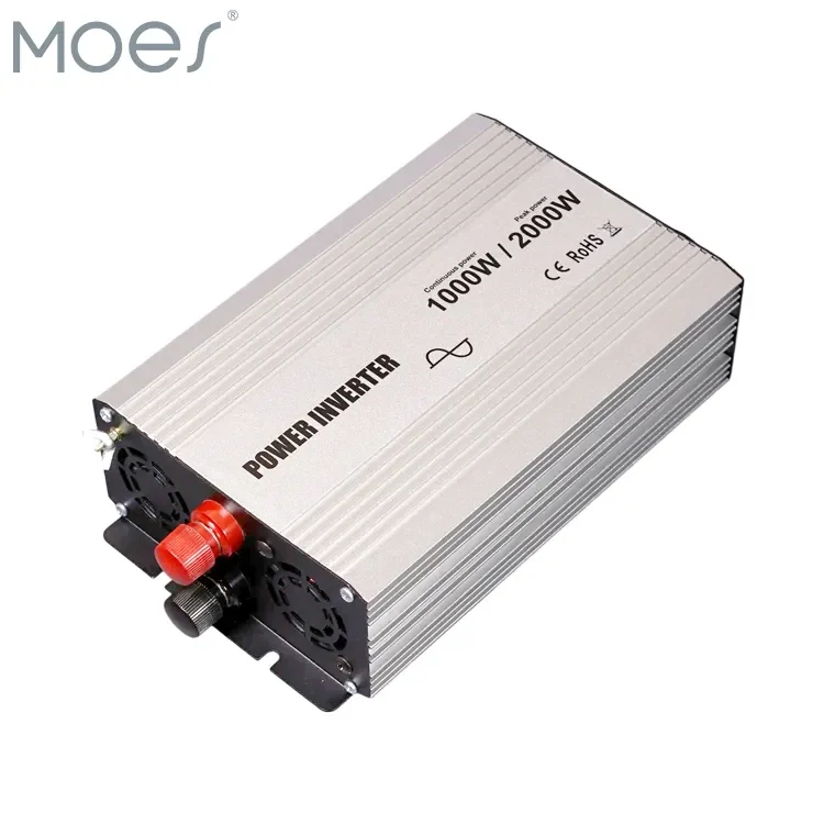
An EV and RV bullet on the page says the unit converts battery DC to AC for onboard electronics and appliances. The same description also names solar systems, UPS duty, and household appliances.
Those are the page’s own sentences. They do not prove every vehicle load or every array is a fit.
For the example listing, the relevant sentence is the battery-DC one. Array voltage, an operating window, and MPPT belong on the solar path page already linked above.
The function page already linked above owns the one-sentence job. The noun page owns the category name.
| Printed place | What it says |
|---|---|
| Parameter table | DC operating voltage, output voltage, operating frequency, range of power |
| Chassis photo | Continuous power and peak power, as those words appear on the photo |
| Description | Pure sine wave, and a high-frequency pure sine class phrase |
| Protection line | Six protection labels, not a certificate list |
The technical table does not print an efficiency percent. The hub does not add one either. Quote desks that need a certified efficiency row should ask for the document that states it, rather than borrow a percent from a general explainer.
Send the product URL, quantity, destination market, and the voltage lines you copied through Contact Us when this listing matches the path. If the source is a PV string, start from the solar path page and the hub instead.
No. The DC source provides the energy.
The chassis changes the form of that energy. An empty battery still means quiet AC outlets.
No. A rectifier turns alternating current into direct current.
An inverter runs the other way, from a DC source toward an AC load. Many power supplies hide a rectifier inside a wall adapter, which is why the two boxes get confused.
A square or stepped wave still alternates, but the corners are sharp and extra harmonics ride along. Motors and audio circuits often show that as buzz or extra heat. Copy the waveform class the listing prints before you promise a quiet load.
Copy the power range the table actually prints, and copy continuous and peak only when those words appear, as they do on this example’s product photo. Leave a blank if a surge row is missing. Do not fill the blank with a multiplier.
Battery direct current enters from storage and is reversed for an AC load. A solar string path starts at array DC and an operating window before its own inversion stage.
Use the solar path page when the drawing shows modules. Use this page when the drawing shows a battery or other stored DC.
The one-sentence role — DC source in, AC loads supplied — lives on the function clarification linked above. This page keeps the order of stages inside that role. The noun clarification keeps the category name.
No. A title can show two watt figures while the table shows a range and the photo shows continuous and peak.
Repeat each string in the place it was printed. The title alone does not relabel the table.



OTHER SMART DEVICES
Jun 13,2026
OTHER SMART DEVICES
Jun 12,2026
TUYA SMART HOME PRODUCTS
Jun 12,2026
 +86 137 3639 3028